Product Description
Products Description
|
Product Name |
HSG Series Hydraulic Cylinder |
|||
|
Work Press |
7/14/16/21/31.5MPa 37.5/63MPa Can be Customized |
|||
|
Material |
Aluminum,Cast Iron,45mnb Steel,Stainless Steel |
|||
|
Bore Size |
40mm–320mm,Customizable |
|||
|
Shaft Diameter |
20mm–220mm,Customizable |
|||
|
Stroke Length |
30mm–14100mm,Customizable |
|||
|
Rod Surface Hardness |
HRC48-54 |
|||
|
Paint Color |
Black,Yellow,Blue,Brown,Customizable |
|||
|
Mounting |
Earring,Flange,Clevis.Foot,Trunnion,Customizable |
|||
|
Warrenty |
1 Year |
|||
|
MOQ |
1 Piece |
|||
|
Delivery Time |
7-15 Days,Also depands on specific demands |
|||
|
Certification |
ISO9001,CE |
|||
Company Profile
QIANGLIN HYDRAULIC MACHINERY CO., LTD
| QiangLin is a professional hydraulic equipment manufacturer, mainly engaged in hydraulic system design, manufacture, installation, transformation, sales, and technical services. Our manufacturing facilities are certified to the ISO 9001 standard. We are an approved supplier to many equipment manufacturers in China. We are also partners with many customers from America, Canada, Australia, Germany, England, and other European Countries. Product quality, shorter delivery time, and customer satisfaction are our long-term commitments to our CHINAMFG customers. Hope to be your partner. |
FAQ:
Q1: Are you a trading company or a manufacturer?
A: We have our own factory.
Q2: Are you able to make Non-standard or customized products?
A: Yes, we can.
Q3: How long is your delivery time?
A: Normally, the delivery time is 7 days if we have stock, 15-30 working days if we don’t. but it
also depends on the product
requirements and quantity.
Q4: Do you provide samples? are the samples free or not?
A: Yes, we can provide samples, but they are not free of charge.
Q5: What are your payment terms?
A: 30% deposit T/T or Irrevocable L/C at sight, If you have any questions, please feel free to
contact us.
Q6: What are your After-sales services?
A: Before shipment, Each individual product will be strictly inspected on our factory QC Process
System. In addition, We have a
Customer Service team to respond to customers’ questions within 12 hours. Being helpful in
solving customers’ problems is always our goal.
| Certification: | CE, ISO9001 |
|---|---|
| Pressure: | High Pressure |
| Work Temperature: | Normal Temperature |
| Customization: |
Available
|
|
|---|
.shipping-cost-tm .tm-status-off{background: none;padding:0;color: #1470cc}
|
Shipping Cost:
Estimated freight per unit. |
about shipping cost and estimated delivery time. |
|---|
| Payment Method: |
|
|---|---|
|
Initial Payment Full Payment |
| Currency: | US$ |
|---|
| Return&refunds: | You can apply for a refund up to 30 days after receipt of the products. |
|---|
What advancements in hydraulic cylinder technology have improved sealing and reliability?
Advancements in hydraulic cylinder technology have continuously contributed to improving sealing and reliability in hydraulic systems. These advancements aim to address common challenges such as leakage, wear, and failure of seals, ensuring optimal performance and longevity. Here are several key advancements that have significantly improved sealing and reliability in hydraulic cylinders:
1. High-Performance Sealing Materials:
– The development of advanced sealing materials has greatly improved the sealing capabilities of hydraulic cylinders. Traditional sealing materials like rubber have been replaced or enhanced with high-performance materials such as polyurethane, PTFE (polytetrafluoroethylene), and various composite materials. These materials offer superior resistance to wear, temperature, and chemical degradation, resulting in improved sealing performance and extended seal life.
2. Enhanced Seal Designs:
– Advancements in seal designs have focused on improving sealing efficiency and reliability. Innovative seal profiles, such as lip seals, wipers, and scrapers, have been developed to optimize fluid retention and prevent contamination. These designs provide better sealing performance, minimizing the risk of fluid leakage and maintaining system integrity. Additionally, improved seal geometries and manufacturing techniques ensure tighter tolerances, reducing the potential for seal failure due to misalignment or extrusion.
3. Integrated Seal and Bearing Systems:
– Hydraulic cylinders now incorporate integrated seal and bearing systems, where the sealing elements also serve as bearing surfaces. This design approach reduces the number of components and potential failure points, improving overall reliability. By integrating seals and bearings, the risk of seal damage or displacement due to excessive loads or misalignment is minimized, resulting in enhanced sealing performance and increased reliability.
4. Advanced Coatings and Surface Treatments:
– The application of advanced coatings and surface treatments to hydraulic cylinder components has significantly improved sealing and reliability. Coatings such as chrome plating or ceramic coatings enhance surface hardness, wear resistance, and corrosion resistance. These surface treatments provide a smoother and more durable surface for seals to operate against, reducing friction and improving sealing performance. Moreover, specialized coatings can also provide self-lubricating properties, reducing the need for additional lubrication and enhancing reliability.
5. Sealing System Monitoring and Diagnostic Technologies:
– The integration of monitoring and diagnostic technologies in hydraulic systems has revolutionized seal performance and reliability. Sensors and monitoring systems can detect and alert operators to potential seal failures or leaks before they escalate. Real-time monitoring of pressure, temperature, and seal performance parameters allows for proactive maintenance and early intervention, preventing costly downtime and ensuring optimal sealing and reliability.
6. Computational Modeling and Simulation:
– Computational modeling and simulation techniques have played a significant role in advancing hydraulic cylinder sealing and reliability. These tools enable engineers to analyze and optimize seal designs, fluid flow dynamics, and contact stresses. By simulating various operating conditions, potential issues such as seal extrusion, wear, or leakage can be identified and mitigated early in the design phase, resulting in improved sealing performance and enhanced reliability.
7. Systematic Maintenance Practices:
– Advances in hydraulic cylinder technology have also emphasized the importance of systematic maintenance practices to ensure sealing and overall system reliability. Regular inspection, lubrication, and replacement of seals, as well as routine system flushing and filtration, help prevent premature seal failure and optimize sealing performance. Implementing preventive maintenance schedules and adhering to recommended service intervals contribute to extended seal life and enhanced reliability.
In summary, advancements in hydraulic cylinder technology have led to significant improvements in sealing and reliability. High-performance sealing materials, enhanced seal designs, integrated seal and bearing systems, advanced coatings and surface treatments, sealing system monitoring and diagnostics, computational modeling and simulation, and systematic maintenance practices have all played key roles in achieving optimal sealing performance and increased reliability. These advancements have resulted in more efficient and dependable hydraulic systems, minimizing leakage, wear, and failure of seals, and ultimately improving the overall performance and longevity of hydraulic cylinders in diverse applications.
Can you provide real-world examples of machinery that heavily rely on hydraulic cylinders?
Hydraulic cylinders are widely used in various industries and applications due to their ability to provide powerful and precise linear motion. They play a crucial role in enabling the operation of heavy machinery that requires controlled force and movement. Here are some real-world examples of machinery that heavily rely on hydraulic cylinders:
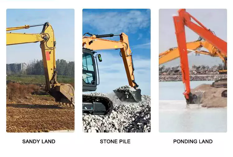
1. Construction Equipment:
– Hydraulic cylinders are extensively used in construction machinery, such as excavators, bulldozers, loaders, and cranes. These machines rely on hydraulic cylinders to perform tasks like lifting heavy loads, extending and retracting booms, tilting buckets, and controlling the movement of various components. Hydraulic cylinders provide the power and precision required to handle the demanding conditions and heavy loads encountered in construction projects.
2. Agricultural Machinery:
– Many agricultural machines, including tractors, combine harvesters, and sprayers, utilize hydraulic cylinders for critical operations. Hydraulic cylinders are used to control the movement of attachments, such as front loaders, backhoes, and plows. They enable functions like lifting and lowering implements, adjusting cutting heights, and controlling the positioning of harvesting equipment. Hydraulic cylinders enhance efficiency and productivity in agricultural operations.
3. Material Handling Equipment:
– Hydraulic cylinders are integral components of material handling equipment, such as forklifts, pallet jacks, and cranes. These machines rely on hydraulic cylinders to lift and lower loads, tilt platforms or forks, and control the movement of lifting mechanisms. Hydraulic cylinders provide the necessary strength and precision to handle heavy loads and ensure safe and efficient material handling operations.
4. Industrial Machinery:
– Various industrial machinery and equipment heavily rely on hydraulic cylinders for critical functions. Examples include hydraulic presses, injection molding machines, metal-forming machines, and hydraulic-powered robots. Hydraulic cylinders enable precise control of force and movement in these applications, allowing for accurate shaping, pressing, and assembly processes.
5. Mining Equipment:
– Hydraulic cylinders are extensively used in mining machinery and equipment. Underground mining machines, such as continuous miners and longwall shearers, utilize hydraulic cylinders for cutting, shearing, and roof support operations. Surface mining equipment, including hydraulic shovels, draglines, and haul trucks, rely on hydraulic cylinders for tasks like bucket movement, boom extension, and vehicle suspension.
6. Automotive Industry:
– The automotive industry extensively utilizes hydraulic cylinders in various applications. Hydraulic cylinders are employed in vehicle suspension systems, power steering systems, convertible tops, and hydraulic brake systems. They enable smooth and controlled movement, precise steering, and efficient braking in automobiles.
7. Aerospace and Aviation:
– Hydraulic cylinders are utilized in aerospace and aviation applications, such as aircraft landing gear systems, wing flaps, and cargo handling equipment. Hydraulic cylinders provide the necessary force and control for extending and retracting landing gear, adjusting wing flaps, and operating cargo doors, ensuring safe and reliable aircraft operations.
8. Marine and Offshore Industry:
– Hydraulic cylinders are essential components in marine and offshore equipment, including ship cranes, winches, and hydraulic-powered anchor systems. They enable lifting, lowering, and positioning of heavy loads, as well as the control of various marine equipment.
These are just a few examples of machinery and industries that heavily rely on hydraulic cylinders. The versatility, power, and precise control offered by hydraulic cylinders make them indispensable in a wide range of applications, where controlled linear motion and force are essential.
What are the common signs of wear or leakage that indicate hydraulic cylinder issues?
Hydraulic cylinders are critical components in hydraulic systems, and wear or leakage can lead to performance issues and potential system failures. It is important to be aware of the common signs that indicate hydraulic cylinder problems. Here’s a detailed explanation of the common signs of wear or leakage that indicate hydraulic cylinder issues:
1. Fluid Leakage:
– Fluid leakage is one of the most obvious signs of hydraulic cylinder problems. If you notice hydraulic fluid leaking from the cylinder, it indicates a seal failure or damage to the cylinder. Leaking fluid may be visible around the rod, piston, or cylinder body. It is important to address fluid leakage promptly as it can lead to a loss of system efficiency, contamination of the surrounding environment, and potential damage to other system components.
2. Reduced Performance:
– Wear or internal damage to the hydraulic cylinder can result in reduced performance. You may notice a decrease in the cylinder’s force output, slower operation, or difficulty in extending or retracting the cylinder. Reduced performance can be indicative of worn seals, damaged piston or rod, internal leakage, or contamination within the cylinder. Any noticeable decrease in the cylinder’s performance should be inspected and addressed to prevent further damage or system inefficiencies.
3. Abnormal Noise or Vibrations:
– Unusual noise or vibrations during the operation of a hydraulic cylinder can indicate internal wear or damage. Excessive noise, knocking sounds, or vibrations that are not typical for the system may suggest problems such as worn bearings, misalignment, or loose internal components. These signs should be investigated to identify the source of the issue and take appropriate corrective measures.
4. Excessive Heat:
– Overheating of the hydraulic cylinder is another sign of potential issues. If the cylinder feels excessively hot to the touch during normal operation, it may indicate problems such as internal leakage, fluid contamination, or inadequate lubrication. Excessive heat can lead to accelerated wear, reduced efficiency, and overall system malfunctions. Monitoring the temperature of the hydraulic cylinder is important to detect and address potential problems.
5. External Damage:
– Physical damage to the hydraulic cylinder, such as dents, scratches, or bent rods, can contribute to wear and leakage issues. External damage can compromise the integrity of the cylinder, leading to fluid leakage, misalignment, or inefficient operation. Regular inspection of the cylinder’s external condition is essential to identify any visible signs of damage and take appropriate actions.
6. Seal Failure:
– Hydraulic cylinder seals are critical components that prevent fluid leakage and maintain system integrity. Signs of seal failure include fluid leakage, reduced performance, and increased friction during cylinder operation. Damaged or worn seals should be replaced promptly to prevent further deterioration of the cylinder’s performance and potential damage to other system components.
7. Contamination:
– Contamination within the hydraulic cylinder can cause wear, damage to seals, and overall system inefficiencies. Signs of contamination include the presence of foreign particles, debris, or sludge in the hydraulic fluid or visible damage to seals and other internal components. Regular fluid analysis and maintenance practices should be implemented to prevent contamination and address any signs of contamination promptly.
8. Irregular Seal Wear:
– Hydraulic cylinder seals can wear over time due to friction, pressure, and operating conditions. Irregular seal wear patterns, such as uneven wear or excessive wear in specific areas, may indicate misalignment or improper installation. Monitoring the condition of the seals during regular maintenance can help identify potential issues and prevent premature seal failure.
It is important to address these common signs of wear or leakage promptly to prevent further damage, ensure the optimal performance of hydraulic cylinders, and maintain the overall efficiency and reliability of the hydraulic system. Regular inspection, maintenance, and timely repairs or replacements of damaged components are key to mitigating hydraulic cylinder issues and maximizing system longevity.

editor by CX 2023-10-28
China Custom Heavy Duty Hydraulic Cylinder for Punching Machines Hydraulic Cylinder Custom for Machines Hydraulic Press Machine Cylinder near me supplier
Product Description
Products Description
|
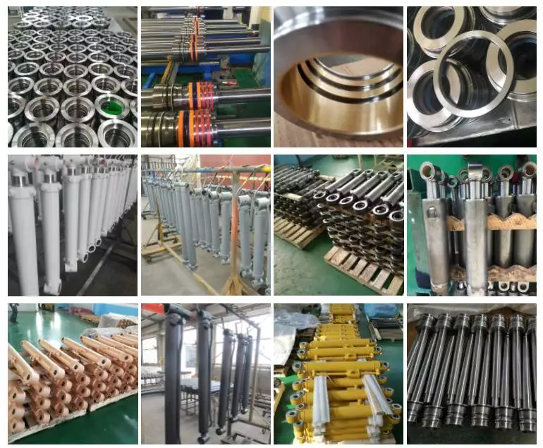
Product Name |
HSG Series Hydraulic Cylinder |
|||
|
Work Press |
7/14/16/21/31.5MPa 37.5/63MPa Can be Customized |
|||
|
Material |
Aluminum,Cast Iron,45mnb Steel,Stainless Steel |
|||
|
Bore Size |
40mm–320mm,Customizable |
|||
|
Shaft Diameter |
20mm–220mm,Customizable |
|||
|
Stroke Length |
30mm–14100mm,Customizable |
|||
|
Rod Surface Hardness |
HRC48-54 |
|||
|
Paint Color |
Black,Yellow,Blue,Brown,Customizable |
|||
|
Mounting |
Earring,Flange,Clevis.Foot,Trunnion,Customizable |
|||
|
Warrenty |
1 Year |
|||
|
MOQ |
1 Piece |
|||
|
Delivery Time |
7-15 Days,Also depands on specific demands |
|||
|
Certification |
ISO9001,CE |
|||
Company Profile
QIANGLIN HYDRAULIC MACHINERY CO., LTD
| QiangLin is a professional hydraulic equipment manufacturer, mainly engaged in hydraulic system design, manufacture, installation, transformation, sales, and technical services. Our manufacturing facilities are certified to the ISO 9001 standard. We are an approved supplier to many equipment manufacturers in China. We are also partners with many customers from America, Canada, Australia, Germany, England, and other European Countries. Product quality, shorter delivery time, and customer satisfaction are our long-term commitments to our worldwide customers. Hope to be your partner. |
FAQ:
Q1: Are you a trading company or a manufacturer?
A: We have our own factory.
Q2: Are you CZPT to make Non-standard or customized products?
A: Yes, we can.
Q3: How long is your delivery time?
A: Normally, the delivery time is 7 days if we have stock, 15-30 working days if we don’t. but it
also depends on the product
requirements and quantity.
Q4: Do you provide samples? are the samples free or not?
A: Yes, we can provide samples, but they are not free of charge.
Q5: What are your payment terms?
A: 30% deposit T/T or Irrevocable L/C at sight, If you have any questions, please feel free to
contact us.
Q6: What are your After-sales services?
A: Before shipment, Each individual product will be strictly inspected on our factory QC Process
System. In addition, We have a
Customer Service team to respond to customers’ questions within 12 hours. Being helpful in
solving customers’ problems is always our goal.
Helical, Straight-Cut, and Spiral-Bevel Gears
If you are planning to use bevel gears in your machine, you need to understand the differences between Helical, Straight-cut, and Spiral bevel gears. This article will introduce you to these gears, as well as their applications. The article will also discuss the benefits and disadvantages of each type of bevel gear. Once you know the differences, you can choose the right gear for your machine. It is easy to learn about spiral bevel gears.
Spiral bevel gear
Spiral bevel gears play a critical role in the aeronautical transmission system. Their failure can cause devastating accidents. Therefore, accurate detection and fault analysis are necessary for maximizing gear system efficiency. This article will discuss the role of computer aided tooth contact analysis in fault detection and meshing pinion position errors. You can use this method to detect problems in spiral bevel gears. Further, you will learn about its application in other transmission systems.
Spiral bevel gears are designed to mesh the gear teeth more slowly and appropriately. Compared to straight bevel gears, spiral bevel gears are less expensive to manufacture with CNC machining. Spiral bevel gears have a wide range of applications and can even be used to reduce the size of drive shafts and bearings. There are many advantages to spiral bevel gears, but most of them are low-cost.
This type of bevel gear has 3 basic elements: the pinion-gear pair, the load machine, and the output shaft. Each of these is in torsion. Torsional stiffness accounts for the elasticity of the system. Spiral bevel gears are ideal for applications requiring tight backlash monitoring and high-speed operations. CZPT precision machining and adjustable locknuts reduce backlash and allow for precise adjustments. This reduces maintenance and maximizes drive lifespan.
Spiral bevel gears are useful for both high-speed and low-speed applications. High-speed applications require spiral bevel gears for maximum efficiency and speed. They are also ideal for high-speed and high torque, as they can reduce rpm without affecting the vehicle’s speed. They are also great for transferring power between 2 shafts. Spiral bevel gears are widely used in automotive gears, construction equipment, and a variety of industrial applications.
Hypoid bevel gear
The Hypoid bevel gear is similar to the spiral bevel gear but differs in the shape of the teeth and pinion. The smallest ratio would result in the lowest gear reduction. A Hypoid bevel gear is very durable and efficient. It can be used in confined spaces and weighs less than an equivalent cylindrical gear. It is also a popular choice for high-torque applications. The Hypoid bevel gear is a good choice for applications requiring a high level of speed and torque.
The Hypoid bevel gear has multiple teeth that mesh with each other at the same time. Because of this, the gear transmits torque with very little noise. This allows it to transfer a higher torque with less noise. However, it must be noted that a Hypoid bevel gear is usually more expensive than a spiral bevel gear. The cost of a Hypoid bevel gear is higher, but its benefits make it a popular choice for some applications.
A Hypoid bevel gear can be made of several types. They may differ in the number of teeth and their spiral angles. In general, the smaller hypoid gear has a larger pinion than its counterpart. This means that the hypoid gear is more efficient and stronger than its bevel cousin. It can even be nearly silent if it is well lubricated. Once you’ve made the decision to get a Hypoid bevel gear, be sure to read up on its benefits.
Another common application for a Hypoid bevel gear is in automobiles. These gears are commonly used in the differential in automobiles and trucks. The torque transfer characteristics of the Hypoid gear system make it an excellent choice for many applications. In addition to maximizing efficiency, Hypoid gears also provide smoothness and efficiency. While some people may argue that a spiral bevel gear set is better, this is not an ideal solution for most automobile assemblies.
Helical bevel gear
Compared to helical worm gears, helical bevel gears have a small, compact housing and are structurally optimized. They can be mounted in various ways and feature double chamber shaft seals. In addition, the diameter of the shaft and flange of a helical bevel gear is comparable to that of a worm gear. The gear box of a helical bevel gear unit can be as small as 1.6 inches, or as large as 8 cubic feet.
The main characteristic of helical bevel gears is that the teeth on the driver gear are twisted to the left and the helical arc gears have a similar design. In addition to the backlash, the teeth of bevel gears are twisted in a clockwise and counterclockwise direction, depending on the number of helical bevels in the bevel. It is important to note that the tooth contact of a helical bevel gear will be reduced by about 10 to 20 percent if there is no offset between the 2 gears.
In order to create a helical bevel gear, you need to first define the gear and shaft geometry. Once the geometry has been defined, you can proceed to add bosses and perforations. Then, specify the X-Y plane for both the gear and the shaft. Then, the cross section of the gear will be the basis for the solid created after revolution around the X-axis. This way, you can make sure that your gear will be compatible with the pinion.
The development of CNC machines and additive manufacturing processes has greatly simplified the manufacturing process for helical bevel gears. Today, it is possible to design an unlimited number of bevel gear geometry using high-tech machinery. By utilizing the kinematics of a CNC machine center, you can create an unlimited number of gears with the perfect geometry. In the process, you can make both helical bevel gears and spiral bevel gears.
Straight-cut bevel gear
A straight-cut bevel gear is the easiest to manufacture. The first method of manufacturing a straight bevel gear was to use a planer with an indexing head. Later, more efficient methods of manufacturing straight bevel gears were introduced, such as the Revacycle system and the Coniflex system. The latter method is used by CZPT. Here are some of the main benefits of using a straight-cut bevel gear.
A straight-cut bevel gear is defined by its teeth that intersect at the axis of the gear when extended. Straight-cut bevel gears are usually tapered in thickness, with the outer part being larger than the inner portion. Straight-cut bevel gears exhibit instantaneous lines of contact, and are best suited for low-speed, static-load applications. A common application for straight-cut bevel gears is in the differential systems of automobiles.
After being machined, straight-cut bevel gears undergo heat treatment. Case carburizing produces gears with surfaces of 60-63 Rc. Using this method, the pinion is 3 Rc harder than the gear to equalize wear. Flare hardening, flame hardening, and induction hardening methods are rarely used. Finish machining includes turning the outer and inner diameters and special machining processes.
The teeth of a straight-cut bevel gear experience impact and shock loading. Because the teeth of both gears come into contact abruptly, this leads to excessive noise and vibration. The latter limits the speed and power transmission capacity of the gear. On the other hand, a spiral-cut bevel gear experiences gradual but less-destructive loading. It can be used for high-speed applications, but it should be noted that a spiral-cut bevel gear is more complicated to manufacture.
Spur-cut bevel gear
CZPT stocks bevel gears in spiral and straight tooth configurations, in a range of ratios from 1.5 to five. They are also highly remachinable except for the teeth. Spiral bevel gears have a low helix angle and excellent precision properties. CZPT stock bevel gears are manufactured using state-of-the-art technologies and know-how. Compared with spur-cut gears, these have a longer life span.
To determine the strength and durability of a spur-cut bevel gear, you can calculate its MA (mechanical advantage), surface durability (SD), and tooth number (Nb). These values will vary depending on the design and application environment. You can consult the corresponding guides, white papers, and technical specifications to find the best gear for your needs. In addition, CZPT offers a Supplier Discovery Platform that allows you to discover more than 500,000 suppliers.
Another type of spur gear is the double helical gear. It has both left-hand and right-hand helical teeth. This design balances thrust forces and provides extra gear shear area. Helical gears, on the other hand, feature spiral-cut teeth. While both types of gears may generate significant noise and vibration, helical gears are more efficient for high-speed applications. Spur-cut bevel gears may also cause similar effects.
In addition to diametral pitch, the addendum and dedendum have other important properties. The dedendum is the depth of the teeth below the pitch circle. This diameter is the key to determining the center distance between 2 spur gears. The radius of each pitch circle is equal to the entire depth of the spur gear. Spur gears often use the addendum and dedendum angles to describe the teeth.

