Product Description
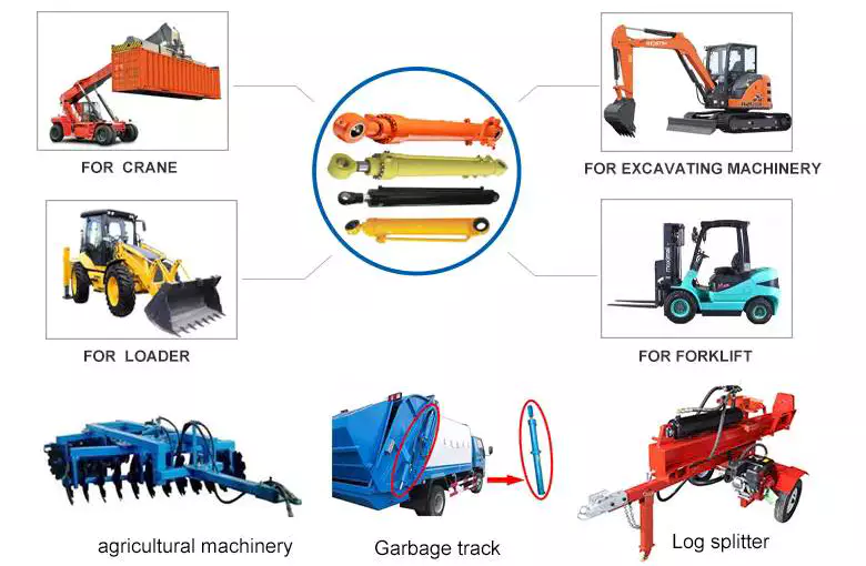
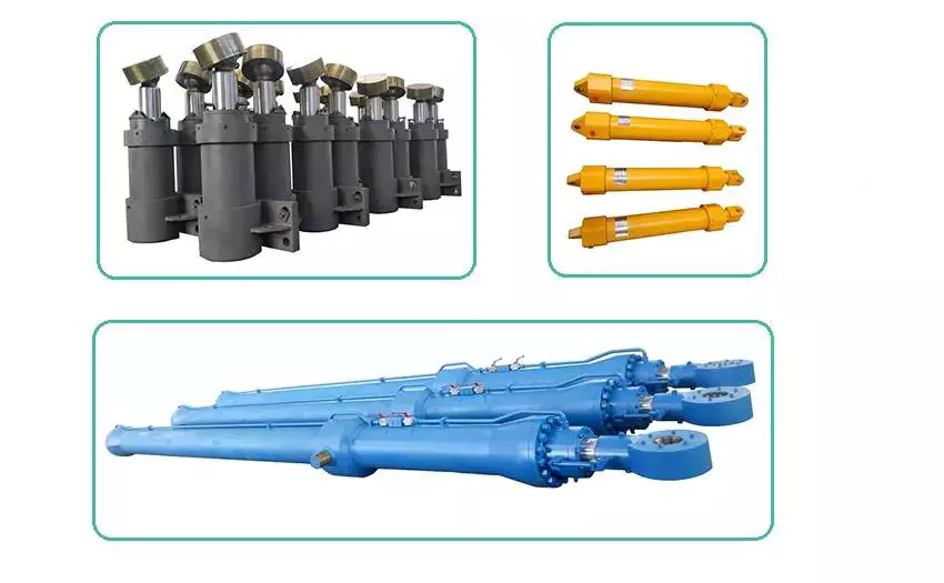
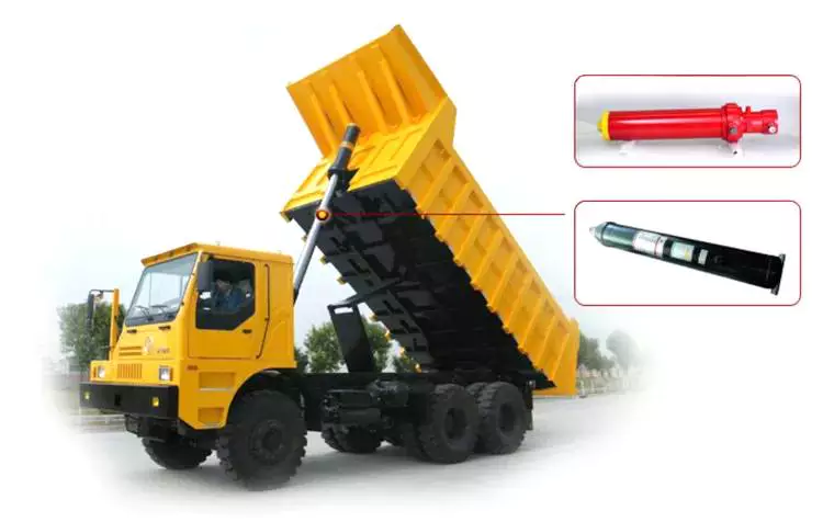
Piston rod chrome plated telescopic hydraulic customized ram cylinder for agricultural machines
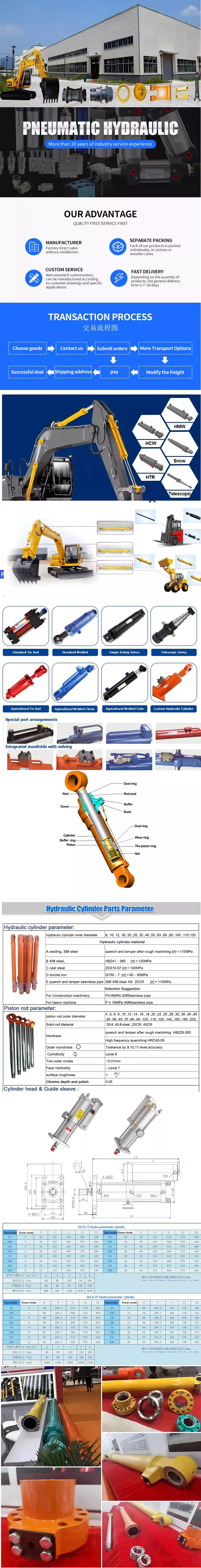
- Product information
- Specification
|
Material
|
Tube – Cold Drawn / Honed Tubing Piston Rod – Chromed, ground & polished 45#steel Rod Seals – Polyurethane U-Cap End Caps – Steel, threaded fixed Wear Ring – Nylon Backup Washer Mounts – Trunnion with angular Swivels |
|
Application
|
Agriculture, Concrete & Asphalt, Cranes, Fire & Rescue,Forestry & Logging,Mining & Rock Crushing,Oil & Gas,Snow & Ice Control,Waste Management and Material Recycling Industry , Engineering Equipment, Special Vehicle, Fitness equipment
|
|
Feature |
1.High quality with a reasonable price 2.ISO9001-2008 3.Customized specification are accepted |
|
Payment |
T/T;L/C,WESTERN UNION |
|
Port |
HangZhou/ZheJiang , China |
|
Quotation |
According to the specific request |
|
MOQ |
According to the product |
|
Packaging
|
metal case;plywood case;carton or as requirement |
|
Delivery time |
30days upon receipt of 30% deposit; or upon receipt of relevant L/C; |
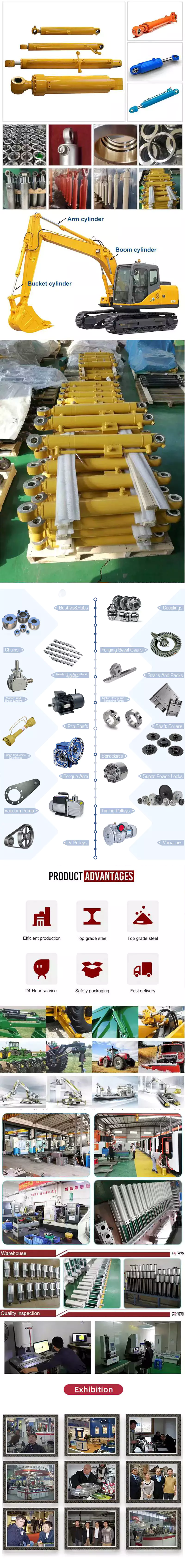
- About us
We specialize in this line for more than 20 years and trader with main products as follows: hydraulic cylinders, hydraulic power units, hydraulic manifolds-blocks, hydraulic flanges,pneumatic cylinders and custom-made components and parts, like industrial valves.
Our sales markets have covered North America, Europe, Australia, Japan and ect.
- Working Process
- Packaging & shipping
- FAQ
Q1: Do you accept OEM manufacturing?
A1: Yes! We do accept OEM manufacturing. We will quote you the exact price and make the exact cylinder according to your specification and drawing.
Q2: Can we design our own package or print our own logo?
A2: Yes! Package and logo will be made acording to your requirements.
Q3: Could we get small quantity samples?
A3: Yes! We understand the quality test is important and we are glad to make the sample for you. The MOQ is 1pcs.
Q4: How long is the production time?
A4: Generally the production time is 30 days.
Q5: What is the warranty?
A5: 12 months against B/L date.
Contact me, any comments will be appreciated.
Ellen Wang
|
Shipping Cost:
Estimated freight per unit. |
To be negotiated |
|---|
| Certification: | CE, ISO9001 |
|---|---|
| Pressure: | Medium Pressure |
| Work Temperature: | Normal Temperature |
| Samples: |
US$ 159/Piece
1 Piece(Min.Order) | Order Sample |
|---|
| Customization: |
Available
|
|
|---|
What advancements in hydraulic cylinder technology have improved sealing and reliability?
Advancements in hydraulic cylinder technology have continuously contributed to improving sealing and reliability in hydraulic systems. These advancements aim to address common challenges such as leakage, wear, and failure of seals, ensuring optimal performance and longevity. Here are several key advancements that have significantly improved sealing and reliability in hydraulic cylinders:
1. High-Performance Sealing Materials:
– The development of advanced sealing materials has greatly improved the sealing capabilities of hydraulic cylinders. Traditional sealing materials like rubber have been replaced or enhanced with high-performance materials such as polyurethane, PTFE (polytetrafluoroethylene), and various composite materials. These materials offer superior resistance to wear, temperature, and chemical degradation, resulting in improved sealing performance and extended seal life.
2. Enhanced Seal Designs:
– Advancements in seal designs have focused on improving sealing efficiency and reliability. Innovative seal profiles, such as lip seals, wipers, and scrapers, have been developed to optimize fluid retention and prevent contamination. These designs provide better sealing performance, minimizing the risk of fluid leakage and maintaining system integrity. Additionally, improved seal geometries and manufacturing techniques ensure tighter tolerances, reducing the potential for seal failure due to misalignment or extrusion.
3. Integrated Seal and Bearing Systems:
– Hydraulic cylinders now incorporate integrated seal and bearing systems, where the sealing elements also serve as bearing surfaces. This design approach reduces the number of components and potential failure points, improving overall reliability. By integrating seals and bearings, the risk of seal damage or displacement due to excessive loads or misalignment is minimized, resulting in enhanced sealing performance and increased reliability.
4. Advanced Coatings and Surface Treatments:
– The application of advanced coatings and surface treatments to hydraulic cylinder components has significantly improved sealing and reliability. Coatings such as chrome plating or ceramic coatings enhance surface hardness, wear resistance, and corrosion resistance. These surface treatments provide a smoother and more durable surface for seals to operate against, reducing friction and improving sealing performance. Moreover, specialized coatings can also provide self-lubricating properties, reducing the need for additional lubrication and enhancing reliability.
5. Sealing System Monitoring and Diagnostic Technologies:
– The integration of monitoring and diagnostic technologies in hydraulic systems has revolutionized seal performance and reliability. Sensors and monitoring systems can detect and alert operators to potential seal failures or leaks before they escalate. Real-time monitoring of pressure, temperature, and seal performance parameters allows for proactive maintenance and early intervention, preventing costly downtime and ensuring optimal sealing and reliability.
6. Computational Modeling and Simulation:
– Computational modeling and simulation techniques have played a significant role in advancing hydraulic cylinder sealing and reliability. These tools enable engineers to analyze and optimize seal designs, fluid flow dynamics, and contact stresses. By simulating various operating conditions, potential issues such as seal extrusion, wear, or leakage can be identified and mitigated early in the design phase, resulting in improved sealing performance and enhanced reliability.
7. Systematic Maintenance Practices:
– Advances in hydraulic cylinder technology have also emphasized the importance of systematic maintenance practices to ensure sealing and overall system reliability. Regular inspection, lubrication, and replacement of seals, as well as routine system flushing and filtration, help prevent premature seal failure and optimize sealing performance. Implementing preventive maintenance schedules and adhering to recommended service intervals contribute to extended seal life and enhanced reliability.
In summary, advancements in hydraulic cylinder technology have led to significant improvements in sealing and reliability. High-performance sealing materials, enhanced seal designs, integrated seal and bearing systems, advanced coatings and surface treatments, sealing system monitoring and diagnostics, computational modeling and simulation, and systematic maintenance practices have all played key roles in achieving optimal sealing performance and increased reliability. These advancements have resulted in more efficient and dependable hydraulic systems, minimizing leakage, wear, and failure of seals, and ultimately improving the overall performance and longevity of hydraulic cylinders in diverse applications.
Advancements in Hydraulic Cylinder Technology Improving Corrosion Resistance
Advancements in hydraulic cylinder technology have led to significant improvements in corrosion resistance. Corrosion is a major concern in hydraulic systems, especially in environments where cylinders are exposed to moisture, chemicals, or corrosive agents. These advancements aim to enhance the durability and longevity of hydraulic cylinders. Let’s explore some of the key advancements in hydraulic cylinder technology that have improved corrosion resistance:
- Corrosion-Resistant Materials: The use of corrosion-resistant materials is a fundamental advancement in hydraulic cylinder technology. Stainless steel, for example, offers excellent resistance to corrosion, making it a popular choice in marine, offshore, and other corrosive environments. Additionally, advancements in metallurgy have led to the development of specialized alloys and coatings that provide enhanced corrosion resistance, extending the lifespan of hydraulic cylinders.
- Surface Treatments and Coatings: Various surface treatments and coatings have been developed to protect hydraulic cylinders from corrosion. These treatments can include electroplating, galvanizing, powder coating, and specialized corrosion-resistant coatings. These coatings create a barrier between the cylinder surface and corrosive elements, preventing direct contact and inhibiting the onset of corrosion. The selection of appropriate coatings depends on the specific application and environmental conditions.
- Sealing Technology: Effective sealing systems are crucial in preventing water, moisture, and contaminants from entering the cylinder and causing corrosion. Advancements in sealing technology have led to the development of high-quality seals and advanced sealing designs that offer superior resistance to corrosion. These seals are typically made from materials specifically engineered to withstand corrosive environments, ensuring long-term sealing performance and minimizing the risk of corrosion-related issues.
- Improved Surface Finishes: The surface finish of hydraulic cylinders plays a role in their resistance to corrosion. Advancements in machining and polishing techniques have allowed for smoother and more uniform surface finishes. Smoother surfaces reduce the likelihood of corrosion initiation and make it easier to clean and maintain hydraulic cylinders. Additionally, specialized finishes, such as passivation or chemical treatments, can be applied to further enhance corrosion resistance.
- Environmental Protection Features: Hydraulic cylinders can be equipped with additional features to protect against corrosion. These features may include protective boots, bellows, or shields that guard vulnerable areas from exposure to corrosive agents. By incorporating these protective elements into the design, hydraulic cylinders can withstand harsh environments and minimize the risk of corrosion-related damage.
In summary, advancements in hydraulic cylinder technology have significantly improved corrosion resistance. The use of corrosion-resistant materials, advanced surface treatments and coatings, innovative sealing technology, improved surface finishes, and the incorporation of environmental protection features have all contributed to enhanced durability and longevity of hydraulic cylinders in corrosive environments. These advancements ensure reliable performance and reduce the maintenance and replacement costs associated with corrosion-related issues.
How do hydraulic cylinders generate force and motion using hydraulic fluid?
Hydraulic cylinders generate force and motion by utilizing the principles of fluid mechanics, specifically Pascal’s law, in conjunction with the properties of hydraulic fluid. The process involves the conversion of hydraulic energy into mechanical force and linear motion. Here’s a detailed explanation of how hydraulic cylinders achieve this:
1. Pascal’s Law:
– Hydraulic cylinders operate based on Pascal’s law, which states that when pressure is applied to a fluid in a confined space, it is transmitted equally in all directions. In the context of hydraulic cylinders, this means that when hydraulic fluid is pressurized, the force is evenly distributed throughout the fluid and transmitted to all surfaces in contact with the fluid.
2. Hydraulic Fluid and Pressure:
– Hydraulic systems use a specialized fluid, typically hydraulic oil, as the working medium. This fluid is stored in a reservoir and circulated through the system by a hydraulic pump. The pump pressurizes the fluid, creating hydraulic pressure that can be controlled and directed to various components, including hydraulic cylinders.
3. Cylinder Design and Components:
– Hydraulic cylinders consist of several key components, including a cylindrical barrel, a piston, a piston rod, and various seals. The barrel is a hollow tube that houses the piston and allows for fluid flow. The piston divides the cylinder into two chambers: the rod side and the cap side. The piston rod extends from the piston and provides a connection point for external loads. Seals are used to prevent fluid leakage and maintain hydraulic pressure within the cylinder.
4. Fluid Input and Motion:
– To generate force and motion, hydraulic fluid is directed into one side of the cylinder, creating pressure on the corresponding surface of the piston. This pressure is transmitted through the fluid to the other side of the piston.
5. Force Generation:
– The force generated by a hydraulic cylinder is a result of the pressure applied to a specific surface area of the piston. The force exerted by the hydraulic cylinder can be calculated using the formula: Force = Pressure × Area. The area is determined by the diameter of the piston or the piston rod, depending on which side of the cylinder the fluid is acting upon.
6. Linear Motion:
– As the pressurized hydraulic fluid acts on the piston, it generates a force that moves the piston in a linear direction within the cylinder. This linear motion is transferred to the piston rod, which extends or retracts accordingly. The piston rod can be connected to external components or machinery, allowing the generated force to perform various tasks, such as lifting, pushing, pulling, or controlling mechanisms.
7. Control and Regulation:
– The force and motion generated by hydraulic cylinders can be controlled and regulated by adjusting the flow of hydraulic fluid into the cylinder. By regulating the flow rate, pressure, and direction of the fluid, the speed, force, and direction of the cylinder’s movement can be precisely controlled. This control allows for accurate positioning, smooth operation, and synchronization of multiple cylinders in complex machinery.
8. Return and Recirculation of Fluid:
– After the hydraulic cylinder completes its stroke, the hydraulic fluid on the opposite side of the piston needs to be returned to the reservoir. This is typically achieved through hydraulic valves that control the flow direction, allowing the fluid to return and be recirculated in the system for further use.
In summary, hydraulic cylinders generate force and motion by utilizing the principles of Pascal’s law. Pressurized hydraulic fluid acts on the piston, creating force that moves the piston in a linear direction. This linear motion is transferred to the piston rod, allowing the generated force to perform various tasks. By controlling the flow of hydraulic fluid, the force and motion of hydraulic cylinders can be precisely regulated, contributing to their versatility and wide range of applications in machinery.


editor by CX 2023-09-14