Product Description
Product Description
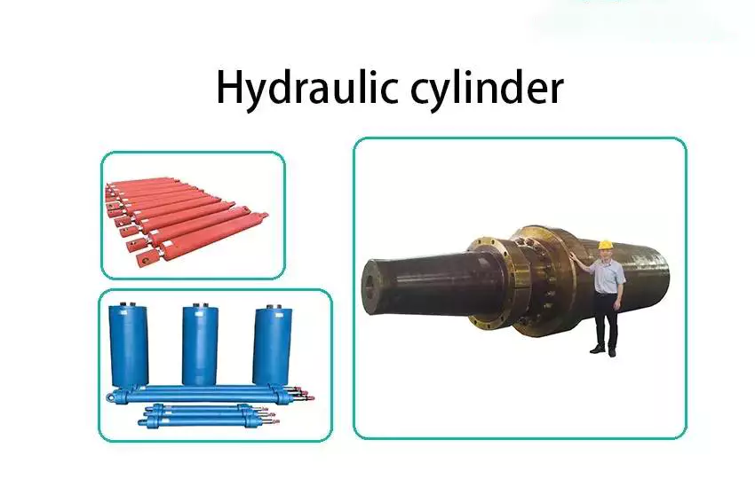
Our company specialized in manufacturing all kinds of hydraulic breaker hammer,breaker hammer pipeline and their accessories as well as excavator attachments, breaker parts has hydraulic breaker chisel,piston, Front & Back head, cylinder, Thrust & Outer bushings, Hammer drill rod and flat pin, hydraulic valve, diaphragm, accumulator, code Seal housing and so on. All the accessories of our pipeline, including clamps, ball valve, foot valve, wire plug, wire alignment, relief valve, lock valve, bracket, connector, hammer tube, arm iron pipe assembly, three-way iron pipe, are independently developed and manufactured by our factory to ensure product quality, safety and reliability.
| part name | hydraulic breaker cylinder front head back head middle cylinder |
| material | 20Crmo, 40Crmo, 42Crmo |
| quality | High quality |
Detailed Photos
Company Profile
HangZhou Changhao Machinery Equipment Co., Ltd. located in Workshop 24, East End of Gangyuan Second Road, No. 33688, CHINAMFG East Road, HangZhou Area of China(ZheJiang ) Pilot Free Trade Zone, HangZhou, Shang dong, China. The workshops occupy an area of 3,000 square meters. The bonded area is supported by national preferential policies and resources are inclined. There is superior terrain, beautiful environment and convenient transportation.
Our company specialized in manufacturing all kinds of hydraulic breaker hammer,breaker hammer pipeline and their accessories as well as excavator attachments, breaker parts has hydraulic breaker chisel,piston, Front & Back head, cylinder, Thrust & Outer bushings, Hammer drill rod and flat pin, hydraulic valve, diaphragm, accumulator, code Seal housing and so on. All the accessories of our pipeline, including clamps, ball valve, foot valve, wire plug, wire alignment, relief valve, lock valve, bracket, connector, hammer tube, arm iron pipe assembly, three-way iron pipe, are independently developed and manufactured by our factory to ensure product quality, safety and reliability.
We have perfect production equipments and test devices. Our company has various international certifications and adopts advanced technology to ensure product quality. We strictly control the material of our products, adopting unique heat treatment technology, special alloy materials, and the quality has reached international advanced level.
We are a manufacturer, CHINAMFG is our brand, the company is not only committed to producing high quality products, but also absolutely guarantee the quality.
Other Products
| After-sales Service: | Online Support |
|---|---|
| Warranty: | 12 Months |
| Type: | Hydraulic Breaker |
| Application: | Excavator |
| Certification: | CE, ISO9001: 2000 |
| Condition: | New |
| Customization: |
Available
|
|
|---|
Can hydraulic cylinders be used for precise operations like CNC machining or molding?
Yes, hydraulic cylinders can be used for precise operations like CNC machining or molding. While hydraulic systems are commonly associated with heavy-duty applications, they can also provide the necessary precision and control required for precise operations in CNC machining and molding processes. Here’s a detailed explanation of how hydraulic cylinders can be utilized for such precise operations:
1. Force and Control:
– Hydraulic cylinders are capable of generating substantial force, which is essential for precise operations in CNC machining and molding. By using hydraulic pressure, the cylinders can deliver the required force to cut or shape materials accurately or exert pressure for molding operations. The hydraulic system allows precise control over the force applied, ensuring consistent and reliable performance.
2. Adjustable Speed and Positioning:
– Hydraulic cylinders offer adjustable speed and precise positioning capabilities, making them suitable for precise operations. By controlling the flow of hydraulic fluid, the speed of the cylinder’s movement can be adjusted according to specific requirements. This adaptability allows for fine-tuning the machining or molding process, achieving the desired precision in material removal or shaping. Hydraulic systems also enable accurate positioning of tools or molds, ensuring precise operations.
3. Integrated Feedback Systems:
– Advanced hydraulic systems can incorporate feedback sensors and control mechanisms to enhance precision in CNC machining and molding. These sensors provide real-time information about the position, speed, and force exerted by the hydraulic cylinders. The control system processes this data and adjusts the flow of hydraulic fluid accordingly, allowing for precise and accurate control over the operations. The feedback systems help maintain consistent performance and compensate for any deviations, ensuring high precision.
4. Damping and Vibration Control:
– Hydraulic cylinders can be equipped with damping mechanisms to minimize vibrations and ensure stability during CNC machining or molding operations. Vibrations can negatively impact precision by causing tool chatter or material deformation. By incorporating cushioning or damping features, hydraulic cylinders help absorb shocks and suppress vibrations, resulting in smoother and more accurate operations.
5. Customization and Adaptability:
– Hydraulic cylinders can be customized and adapted to meet the specific requirements of CNC machining or molding processes. Engineers can design cylinders with unique dimensions, stroke lengths, mounting options, and sealing arrangements to fit into equipment or systems with precise specifications. Customized hydraulic cylinders ensure optimal performance and compatibility for precise operations, enabling seamless integration into CNC machines or molding equipment.
6. Energy Efficiency:
– Hydraulic systems can be designed to be energy-efficient, contributing to cost savings in CNC machining or molding operations. By utilizing variable speed pumps, efficient control valves, and well-designed hydraulic circuits, energy consumption can be optimized. This efficiency reduces heat generation, leading to improved stability and precision in operations while minimizing energy costs.
7. Maintenance and Calibration:
– Regular maintenance and calibration of hydraulic systems are essential to maintain their precision in CNC machining or molding applications. Proper lubrication, inspection of seals, and replacement of worn-out components help ensure optimal performance. Regular calibration of control systems and feedback sensors ensures accurate readings and reliable operation, contributing to precision in machining or molding processes.
In summary, hydraulic cylinders can be effectively used for precise operations like CNC machining or molding. Their ability to generate substantial force, adjustable speed and positioning, integration with feedback systems, damping and vibration control, customization and adaptability, energy efficiency, and proper maintenance contribute to achieving the required precision in these operations. By leveraging the strengths of hydraulic systems, manufacturers can enhance the accuracy and reliability of CNC machining or molding processes, resulting in high-quality products and improved productivity.
Contribution of Hydraulic Cylinders to the Precision of Robotic and Automation Systems
Hydraulic cylinders play a significant role in enhancing the precision of robotic and automation systems. These systems rely on precise and controlled movements to perform various tasks with accuracy and repeatability. Let’s explore how hydraulic cylinders contribute to the precision of robotic and automation systems:
- Precise Positioning: Hydraulic cylinders enable precise positioning of robotic arms or automation components. They provide accurate control over the linear motion required for tasks such as picking, placing, and assembly. By precisely controlling the extension and retraction of the hydraulic cylinder, the system can achieve the desired position with high accuracy, ensuring precise alignment and consistent results.
- Controlled Motion: Hydraulic cylinders offer controlled and smooth motion, which is crucial for precise operation in robotic and automation systems. The flow of hydraulic fluid can be precisely regulated to control the speed and acceleration of the cylinder’s movement. This precise control allows for gentle and controlled movements, minimizing vibrations, overshooting, or jerky motions that could affect the accuracy of the system.
- Force Control: Hydraulic cylinders provide force control capabilities that contribute to precision in robotic and automation systems. By adjusting the hydraulic pressure, the force exerted by the cylinder can be precisely controlled. This is particularly valuable in applications that require delicate force-sensitive tasks, such as gripping fragile objects or performing precise force feedback during assembly or testing processes.
- Load Handling: Hydraulic cylinders are capable of handling heavy loads, allowing robotic and automation systems to manipulate and transport objects with precision. The high force capabilities of hydraulic cylinders ensure secure and stable handling of loads, minimizing the risk of slippage or imprecise positioning. This is crucial in applications where precise control over heavy objects is required, such as material handling or industrial assembly processes.
- Durability and Reliability: Hydraulic cylinders are known for their durability and reliability in demanding industrial environments. The ability to withstand repeated use, high loads, and harsh conditions ensures consistent performance over time. This reliability contributes to the precision of robotic and automation systems, as any deviation or failure in the cylinder’s movement could lead to inaccuracies or disruptions in the system’s operation.
In summary, hydraulic cylinders make significant contributions to the precision of robotic and automation systems by enabling precise positioning, controlled motion, force control, load handling, and offering durability and reliability. These capabilities ensure accurate and repeatable movements, minimize errors, and enhance the overall precision of the system. By incorporating hydraulic cylinders into robotic and automation systems, manufacturers can achieve higher levels of precision, efficiency, and productivity in various industrial applications.
How do manufacturers ensure the quality and compatibility of hydraulic cylinders?
Manufacturers employ various measures to ensure the quality and compatibility of hydraulic cylinders, ensuring that they meet industry standards, performance requirements, and the specific needs of their customers. Here’s a detailed explanation of the methods and practices used by manufacturers to ensure the quality and compatibility of hydraulic cylinders:
1. Design and Engineering:
– Manufacturers employ skilled engineers and designers who have expertise in hydraulic systems and cylinder design. They use advanced design software and tools to create hydraulic cylinders that meet the desired specifications and performance requirements. Through careful analysis and simulation, manufacturers can ensure that the cylinders are designed to function optimally and provide the necessary force, stroke length, and reliability.
2. Material Selection:
– High-quality materials are crucial for the durability, performance, and compatibility of hydraulic cylinders. Manufacturers carefully select materials such as steel or other alloys based on their strength, corrosion resistance, and suitability for hydraulic applications. They source materials from reputable suppliers and perform quality checks to ensure that the materials meet the required standards and specifications.
3. Quality Control:
– Manufacturers implement robust quality control processes throughout the production of hydraulic cylinders. This includes rigorous inspections and tests at various stages of manufacturing, from raw material inspection to final assembly. Quality control personnel perform dimensional checks, surface finish inspections, and functional tests to verify that the cylinders meet the specified tolerances, performance criteria, and compatibility requirements.
4. Testing and Validation:
– Hydraulic cylinders undergo testing and validation procedures to ensure their performance, reliability, and compatibility. Manufacturers conduct various tests, such as pressure testing, leakage testing, load testing, and endurance testing. These tests simulate real-world operating conditions and verify that the cylinders can withstand the expected loads, pressures, and environmental factors. Additionally, manufacturers may perform compatibility testing to ensure that the cylinders can integrate seamlessly with other hydraulic system components.
5. Compliance with Standards:
– Manufacturers adhere to industry standards and regulations to ensure the quality and compatibility of hydraulic cylinders. They follow standards such as ISO 9001 for quality management systems and ISO 6020/2 or ISO 6022 for hydraulic cylinders. Compliance with these standards ensures that the manufacturing processes, quality control measures, and product performance meet internationally recognized benchmarks.
6. Certification and Accreditation:
– Manufacturers may obtain certifications and accreditations from recognized organizations to demonstrate their commitment to quality and compatibility. Certifications such as ISO certifications or third-party certifications provide assurance to customers that the hydraulic cylinders have undergone rigorous evaluations and meet specific quality and compatibility standards.
7. Customer Collaboration:
– Manufacturers actively engage with customers to understand their specific requirements and ensure compatibility. They work closely with customers to gather application-specific details, such as operating conditions, load requirements, and environmental factors. This collaborative approach allows manufacturers to customize hydraulic cylinders and provide solutions that are perfectly matched to the customer’s needs, ensuring compatibility and optimal performance.
8. Continuous Improvement:
– Manufacturers are committed to continuous improvement in their processes and products. They invest in research and development to incorporate the latest technologies, materials, and manufacturing techniques. By staying updated with industry advancements, manufacturers can enhance the quality, performance, and compatibility of their hydraulic cylinders over time.
By implementing effective design and engineering practices, selecting high-quality materials, conducting rigorous quality control, testing and validation procedures, complying with industry standards, obtaining certifications, collaborating with customers, and embracing continuous improvement, manufacturers ensure the quality and compatibility of hydraulic cylinders. These measures help to deliver reliable, high-performance cylinders that meet the diverse needs of industries and applications.

editor by CX 2023-09-18
China OEM Furukawa F12 F19 F20 F22 F27 Hydraulic Hammer Cylinder with Great quality
Product Description
ARE YOU LOOKING FOR A RELIABLE FACTORY FOR HYDRAULIC BREAKER SPARE PARTS WITH
STABLE QUALITY & AFTER-SALES SERVICE GUARANTEES?
DO YOU HAVE CLIENTS WHO WANT TO BUY THE DURABLE LONG LIFETIME & HIGH-END FINISH
HYDRAULIC HAMMER SPARE PARTS AS JAPAN OR KOREA’S?
ARE YOU FINDING JAPAN/KOREA SUPPLIERS’ OFFER SO HIGH AND THINK ABOUT
A BETTER ECONOMIC ALTERNATIVE?
HOW ABOUT A PERSON HELP YOU TO SOLVE ALL THE PROBLEMS AND LEAVE YOU
TO SIT BACK AND RELAX?
Hi, I am Ryan, I have 8 years of international trade sales experience and now working for
HangZhou Zhongye Machinery Manufacture Co., Ltd.
I know you are looking for high-quality SPARE PARTS while affordable like this:
Now you can stop searching and comparison, I bet our factory can be your best choice. WHY?
1, Stable quality in various actual fields worldwide
Our chisels have been supplied to over 70 companies of more than 30 countries
Certificate such as CE, ISO, can also be a proof of our quality.
2, Well equipped production facility.
The one-stop operational resource that covers 2 manufacturing factories for hydraulic breaker, chisel,
and spare parts which 10 years’ history Zhongye machinery factory for mid-range products.
Second NEW factory with an up-to-date production facility for high-end hydraulic breaker, chisel, and spare parts;
Third, We have pistons for the following hydraulic breaker/hammers:
you can also send us your drawing for mass customized production.
| Brand Name |
Below models are part of hydraulic breaker models for your refference. |
| Soosan | SB40 SB43 SB45 SB50 SB60 SB81N SB81 SB81A SB100 SB121 SB130 SB140 SB151 |
| Furukawa | HB20G HB30G HB40G HB8G HB10G HB5G HB15G F19 F20 F22 F35 F70 FX47 F45 FS37 F27 FS22 F27 F12 F9 F6 |
| Toku | TNB150 TNB151 TNB14E TNB5M TNB4E TNB6E TNB7E TNB14B TNB14 TNB190 TNB230 |
| General | GB8AT GB8T GB8F GB2T GB5T GB4T GB6T GB540E GB580E |
| NPK | H2X NPK H4X NPK H6X NPK H-7X NPK H-9X NPK H-10X H-10XB E-12X E210A/B NPK NPK H12XB NPK H14X NPK H20X |
| Daemo | S2100 S2200 S2300 S3000 |
| Krup | HM960 HM951 HM720 HM980 HM1000 HM1500 |
| MSB | MS600 Xihu (West Lake) Dis.350 |
| Okada | OUB308 OUB312 OUB316 |
| Toy | THBB401 THBB801 THBB1600 THBB2000 |
| Hanwoo | RHB323 RHB313 RHB305 RHB325 RHB326 RHB328 RHB330 RHB340 RHB350 |
3, Years of accumulated Art-Heat Treatment Technology
10 years of accumulated heat treatment technology, making the our spare parts 2 TIMES durable than most small workshops.
4, Quality Assurance
Every working procedure would influence the product quality, thus each working procedure should
sustaining testing on our production lines. Our warranty policy could make you rest easy.
5, After-sales service
With my 8 years’ export experience, I was confident I could ensure the smooth process from order
receiving until the order arrives at your hand.
Hence, Zhongye is available to show you our product range and CZPT you in the choice of the products that best fit your needs,
Isn’t good enough?
I have a trade secret can make your business more profitable and competitive.
I guess most of your competitors haven’t known that,
Just send me your detailed inquiry at the bottom and I will share it with you for free.
Grab the opportunity today! or your competitors may have learned that.
Overview of Different Types of Pulleys
A pulley is a wheel mounted on a shaft or shaft. Its purpose is to facilitate the movement or change of direction of the cable or taut rope, and to transmit power between the cable and the shaft. Pulleys are typically used for lifting, winding or forklift applications. If you are building your own pulley system, the following design and installation considerations should be followed. This article will give you an overview of the different types of pulleys.
Pulley System Mechanics
There are many different ways to utilize the mechanism of the pulley system. The most basic pulley system consists of a fixed wheel and a support frame. Both components are connected by ropes or cables used to support the load. A pulley system is effective when the force required to lift the load is less than the weight of the object being lifted.
One way to use a pulley system is to suspend a block with a mass of 0.80 kg on a fixed pulley. Then another person can hang a bucket weighing up to 40kg. The weight of the bucket is transferred to the fixed pulley. The rope is attached to the pulley by a loop or sling. The rope will spin and pull on the barrel or block.
The pulley system is also an important tool for lifting heavy objects. Pulleys are often used in construction equipment to make lifting heavy objects easier. Gun tackles, yard tackles, and stationary tackle systems are common examples of these devices. They use the mechanical advantage of the design to guide the force that lifts the object. If you want to learn more about pulley systems, visit Vedantu. This website will provide you with a full description of the mechanism and its application.
Types of pulleys
Many different types of pulleys are used to lift heavy objects. They change the direction of the force and are an integral part of the cable system. Therefore, pulleys can move large and heavy objects more easily. However, before buying a pulley, you should have an idea of the benefits it brings. Below are some of the most common uses for pulleys.
Conical Pulley: Consists of several small conical pulleys connected to each other. The larger base of 1 pulley is used to guide the force. Round pulleys are used in the same way as step pulleys. They are widely used in industry and can be purchased at any hardware store. Pulleys are a huge investment, and the benefits they provide far outweigh the cost.
Movable Pulls: These are similar to their names, but work by allowing objects to move with the pull. Their movable parts are attached to the object to be lifted. They are also ideal for lifting heavy loads and can be found in utility elevators and construction cranes. They are also used in many other industries. They can also be made of wood, plastic or metal. The type of pulley you use depends on its intended use.
Mechanical Advantages of Pulley Systems
A pulley system is a simple machine that reduces the effort required to lift heavy loads. This mechanical advantage is proportional to the number of loops. For example, if you have a single rope loop, you must apply equal force to lift the weight. When you add another rope loop, you can lift heavier weights just by applying the same force. Therefore, a pulley system is an excellent way to use gravity to your advantage.
Mechanical advantage is a measure of the effectiveness of a pulley system. This ratio of force to work is called the mechanical advantage. In other words, if the rope system has a large mechanical advantage, it means that it requires less force to lift heavier loads. This advantage is usually measured in kilograms and is the same for all pulley systems. In general, the greater the mechanical advantage, the less effort is required to lift the load.
The mechanical advantage of a pulley system is that a single movable pulley requires half the force to lift an object than a single fixed pulley. Assuming frictionless bearings, the MA of a single pulley system is 2, similar to the MA of a single lever. A single pulley travels twice as much as it takes to move heavy objects manually.
Considerations when designing and installing a pulley system
The capacity of the pulley depends on the type and diameter of the cable. Besides its diameter, its sheath should also support it well. The basic function of the pulley is also important. However, most people tend to ignore the pulley selection process, resulting in ineffective load-pull capabilities. To avoid such problems, different parameters must be carefully considered during design and installation.
During the design and installation of the pulley system, the ratio of the cable diameter to the largest pulley diameter must be considered. Those who work in the industrial sector will have an idea of this ratio. The greater the D:d ratio, the greater the capacity of the cable to withstand the load. The best way to ensure secure design is to take the right information and use it to design a system that is both robust and secure.
When designing a pulley system, it is important to remember that the pulley needs to have enough power to operate safely. In addition to horsepower, the belt should have sufficient elongation to absorb shock loads. If the elongation of the belt is very small, it is very likely that the teeth will be sheared or broken, causing serious damage to the system. Extensive belt sag should be compensated for by offsetting the driven pulley. Finally, the frame supporting the pulley should be rigid. Otherwise, the non-rigid frame will cause center distance and tooth skipping changes.
Add more pulleys to the system
Adding more pulleys to the spool might have some effect. The friction between the rope and the pulley increases with the number of pulleys, which in practice limits the number of spools. The best solution is to combine the pulleys into 1 housing. If the load is small enough, adding a few pulleys probably won’t make a difference.
Using multiple pulleys allows a single load to be lifted with half the force required. The longer the rope, the greater the mechanical advantage. In fact, a spool can withstand a load of 100 N. Additionally, adding more pulleys quadrupled the mechanical advantage. In this case, a single 100 N load would require a force of 25 Newtons.
When the rope is used, it stretches as the weight of the object increases. This will make the rope longer, increasing its length and increasing the distance over which the load can be lifted. Eventually, the rope will break and the lifted object will fall. Then you will have to buy a new rope. It may seem like an expensive proposition, but it pays off in the long run.
cast iron pulley
Cast iron pulleys are the most popular choice among industrial users. They are made of solid cast iron and usually cost very little. Their rims are held in place by a mesh that extends from a central boss. They also have spokes and arms that hold them in place. These pulleys are ideal for a variety of applications including fan belts, compressors and conveyors.
V-groove drive pulleys are ideal for general purpose pulleys. It has an inner diameter of 1 inch and is commonly used in feeders and ventilation curtain systems. Its steel straps prevent rust and ensure it meets or exceeds industry standards. 3-1/2″ cast iron pulleys are also available. In addition to the V-groove drive pulley, there are similar pulleys for power transmission. The V-groove drive pulley is powder coated for added durability.
The cross section of the arm is elliptical, with the long axis twice as long as the short axis. The radius of the arm is equal to the diameter of the pulley. The thickness of the arm is a key factor to consider when purchasing a pulley. If you’re not sure which material you need, you can always consider wooden or steel pulleys. They are lighter and have a higher coefficient of friction than metal pulleys.
timing pulley
Plastic timing pulleys have many advantages over steel timing pulleys. On the 1 hand, they are lightweight and corrosion resistant, making them ideal for applications that do not require high torque and tensile strength. Another benefit is their resistance to high temperatures. Plastic timing pulleys are ideal for applications involving flammable gases, solvents or particles. They can last for many years. For more information on the different types of plastic timing pulleys.
Vertical shaft drives require flanged timing pulleys. For large span drives, at least 1 of these pulleys must be flanged. The flange provides a secure connection to the shaft and prevents ratcheting of the timing belt. Finally, HTD timing belt teeth prevent timing belt ratcheting. These teeth need a large enough space to be seated. However, they can also cause a backlash. These pulleys are not suitable for applications where positional accuracy is critical.
Timing belt systems are designed to avoid such problems. The drive shaft and the driven shaft are aligned with each other. The pulleys are located on different planes and are connected by pitch lines. The pitch line of the timing pulley coincides with the pitch line of the belt. These pulleys are also easier to implement and maintain. It is better to use a synchronous system because the resulting gear system emits less noise than other systems.


China supplier Hydraulic Hammer Front Head Cylinder with Great quality
Product Description
Box Types of Hydraulic Breakers rock hammer for excavator breaker
High quality and competitive price
.Good after-sale service
.Contact with us to get more information
.Looking forward to cooperate with you
| TYPE NAME | MODEL | TYPE NAME | MODEL | TYPE NAME | MODEL |
| FURUKAWA | HB100 | GENERAL BREAKER | GB1T | SOOSAN | SH200 |
| FURUKAWA | HB200 | GENERAL BREAKER | GB2T | SOOSAN | SH400 |
| FURUKAWA | HB700 | GENERAL BREAKER | GB3T | SOOSAN | SH700 |
| FURUKAWA | HB5G | GENERAL BREAKER | GB4T | SOOSAN | SH-18G |
| FURUKAWA | HB8G | GENERAL BREAKER | GB5T | SOOSAN | SH-20G |
| FURUKAWA | HB10G | GENERAL BREAKER | GB6T | SOOSAN | SH-30G |
| FURUKAWA | HB15G | GENERAL BREAKER | GB8F | SOOSAN | SH-35G |
| FURUKAWA | HB20G | GENERAL BREAKER | GB8T | SOOSAN | SH-40G |
| FURUKAWA | HB30G | GENERAL BREAKER | GB11T | SOOSAN | SB-30 |
| FURUKAWA | HB40G | GENERAL BREAKER | GB14T | SOOSAN | SB-35 |
| FURUKAWA | HB50G | GENERAL BREAKER | GB8AT | SOOSAN | SB-40 |
| FURUKAWA | HB1200 | GENERAL BREAKER | GB170E | SOOSAN | SB-43 |
| FURUKAWA | F5 | GENERAL BREAKER | GB220E | SOOSAN | SB-45 |
| FURUKAWA | F6 | GENERAL BREAKER | GB290E | SOOSAN | SB-50 |
| FURUKAWA | F9 | GENERAL BREAKER | GB300E | SOOSAN | SB-60 |
| FURUKAWA | F12 | GENERAL BREAKER | GB320E | SOOSAN | SB-70 |
| FURUKAWA | F19 | GENERAL BREAKER | GB400E | SOOSAN | SB-81 |
| FURUKAWA | F22 | GENERAL BREAKER | GB526E | SOOSAN | SB-100 |
| FURUKAWA | F27 | SOOSAN | SB-121 | ||
| FURUKAWA | F35 | SOOSAN | SB-131 | ||
| FURUKAWA | F45 | SOOSAN | SB-151 | ||
| FURUKAWA | F70 |
Product process:
Forging- – Turnery- – Heat treatment- – Painting- – Inspection
*Our promise:
=== Small order is acceptable
=== OEM is acceptable
=== Any third party testing is acceptable
=== 12Months quality guarantee
24 hours service for you! We are waiting for you!
*Specification of chisel:
*1. Full size & large supply;
* 2. Factory supplier
*3. Applications:
A. Cone—universal tool
B. Wedged—demolition work, road construction, bridge foundation
C. Blunt—mining, quarring, crushing rock
D. Moil point—demolition work, road construction, bridge foundation
* 4. Surface: Smooth
* 5. Delivery time: Within10days after receipt of deposit asap.;
* 6. Packing: Standard exporting package & as customers’ need.
*Our advantage:
* 1. Price——Competitive price=We produce, which greatly reduce our cost!
*2. Product—Special alloy steel+ special smithing technics+ special heat
Treatment method+ superior performance and price ratio
*3. Expertise–We have a technician team and a QC team, which ensure
Our products is exactly what you want.
* 4. Productivity——We have large-scale production line, which guarantee
All your orders will be finished in earlist time
*5. Materials———-All chisels are made of high-quality raw materials.
* 6. Service————-We are on standby for your best service
If you need other reletive information please check our website and contact me directly.
FAQ
Q: Are you trading company or manufacturer ?
A: We are factory.
Q: How long is your delivery time?
A: Generally it is 5-10 days if the goods are in stock. or it is 15-20 days if the goods are not in stock, it is according to quantity.
Q: Do you provide samples ? is it free or extra ?
A: Yes, we could offer the sample for free charge but do not pay the cost of freight.
Q: What is your terms of payment ?
A: Payment=1000USD, 30% T/T in advance ,balance before shippment.
If you have other requirements,please feel free to contact with Irene Mei.
Send your inquiry details in the below, and click “send” Now ! ↓↓↓↓↓↓
Screw Shaft Features Explained
When choosing the screw shaft for your application, you should consider the features of the screws: threads, lead, pitch, helix angle, and more. You may be wondering what these features mean and how they affect the screw’s performance. This article explains the differences between these factors. The following are the features that affect the performance of screws and their properties. You can use these to make an informed decision and purchase the right screw. You can learn more about these features by reading the following articles.
Threads
The major diameter of a screw thread is the larger of the 2 extreme diameters. The major diameter of a screw is also known as the outside diameter. This dimension can’t be directly measured, but can be determined by measuring the distance between adjacent sides of the thread. In addition, the mean area of a screw thread is known as the pitch. The diameter of the thread and pitch line are directly proportional to the overall size of the screw.
The threads are classified by the diameter and pitch. The major diameter of a screw shaft has the largest number of threads; the smaller diameter is called the minor diameter. The thread angle, also known as the helix angle, is measured perpendicular to the axis of the screw. The major diameter is the largest part of the screw; the minor diameter is the lower end of the screw. The thread angle is the half distance between the major and minor diameters. The minor diameter is the outer surface of the screw, while the top surface corresponds to the major diameter.
The pitch is measured at the crest of a thread. In other words, a 16-pitch thread has a diameter of 1 sixteenth of the screw shaft’s diameter. The actual diameter is 0.03125 inches. Moreover, a large number of manufacturers use this measurement to determine the thread pitch. The pitch diameter is a critical factor in successful mating of male and female threads. So, when determining the pitch diameter, you need to check the thread pitch plate of a screw.
Lead
In screw shaft applications, a solid, corrosion-resistant material is an important requirement. Lead screws are a robust choice, which ensure shaft direction accuracy. This material is widely used in lathes and measuring instruments. They have black oxide coatings and are suited for environments where rusting is not acceptable. These screws are also relatively inexpensive. Here are some advantages of lead screws. They are highly durable, cost-effective, and offer high reliability.
A lead screw system may have multiple starts, or threads that run parallel to each other. The lead is the distance the nut travels along the shaft during a single revolution. The smaller the lead, the tighter the thread. The lead can also be expressed as the pitch, which is the distance between adjacent thread crests or troughs. A lead screw has a smaller pitch than a nut, and the smaller the lead, the greater its linear speed.
When choosing lead screws, the critical speed is the maximum number of revolutions per minute. This is determined by the minor diameter of the shaft and its length. The critical speed should never be exceeded or the lead will become distorted or cracked. The recommended operational speed is around 80 percent of the evaluated critical speed. Moreover, the lead screw must be properly aligned to avoid excessive vibrations. In addition, the screw pitch must be within the design tolerance of the shaft.
Pitch
The pitch of a screw shaft can be viewed as the distance between the crest of a thread and the surface where the threads meet. In mathematics, the pitch is equivalent to the length of 1 wavelength. The pitch of a screw shaft also relates to the diameter of the threads. In the following, the pitch of a screw is explained. It is important to note that the pitch of a screw is not a metric measurement. In the following, we will define the 2 terms and discuss how they relate to 1 another.
A screw’s pitch is not the same in all countries. The United Kingdom, Canada, and the United States have standardized screw threads according to the UN system. Therefore, there is a need to specify the pitch of a screw shaft when a screw is being manufactured. The standardization of pitch and diameter has also reduced the cost of screw manufacturing. Nevertheless, screw threads are still expensive. The United Kingdom, Canada, and the United States have introduced a system for the calculation of screw pitch.
The pitch of a lead screw is the same as that of a lead screw. The diameter is 0.25 inches and the circumference is 0.79 inches. When calculating the mechanical advantage of a screw, divide the diameter by its pitch. The larger the pitch, the more threads the screw has, increasing its critical speed and stiffness. The pitch of a screw shaft is also proportional to the number of starts in the shaft.
Helix angle
The helix angle of a screw shaft is the angle formed between the circumference of the cylinder and its helix. Both of these angles must be equal to 90 degrees. The larger the lead angle, the smaller the helix angle. Some reference materials refer to angle B as the helix angle. However, the actual angle is derived from calculating the screw geometry. Read on for more information. Listed below are some of the differences between helix angles and lead angles.
High helix screws have a long lead. This length reduces the number of effective turns of the screw. Because of this, fine pitch screws are usually used for small movements. A typical example is a 16-mm x 5-inch screw. Another example of a fine pitch screw is a 12x2mm screw. It is used for small moves. This type of screw has a lower lead angle than a high-helix screw.
A screw’s helix angle refers to the relative angle of the flight of the helix to the plane of the screw axis. While screw helix angles are not often altered from the standard square pitch, they can have an effect on processing. Changing the helix angle is more common in two-stage screws, special mixing screws, and metering screws. When a screw is designed for this function, it should be able to handle the materials it is made of.
Size
The diameter of a screw is its diameter, measured from the head to the shaft. Screw diameters are standardized by the American Society of Mechanical Engineers. The diameters of screws range from 3/50 inches to 16 inches, and more recently, fractions of an inch have been added. However, shaft diameters may vary depending on the job, so it is important to know the right size for the job. The size chart below shows the common sizes for screws.
Screws are generally referred to by their gauge, which is the major diameter. Screws with a major diameter less than a quarter of an inch are usually labeled as #0 to #14 and larger screws are labeled as sizes in fractions of an inch. There are also decimal equivalents of each screw size. These measurements will help you choose the correct size for your project. The screws with the smaller diameters were not tested.
In the previous section, we described the different shaft sizes and their specifications. These screw sizes are usually indicated by fractions of an inch, followed by a number of threads per inch. For example, a ten-inch screw has a shaft size of 2” with a thread pitch of 1/4″, and it has a diameter of 2 inches. This screw is welded to a two-inch Sch. 40 pipe. Alternatively, it can be welded to a 9-inch O.A.L. pipe.
Shape
Screws come in a wide variety of sizes and shapes, from the size of a quarter to the diameter of a U.S. quarter. Screws’ main function is to hold objects together and to translate torque into linear force. The shape of a screw shaft, if it is round, is the primary characteristic used to define its use. The following chart shows how the screw shaft differs from a quarter:
The shape of a screw shaft is determined by 2 features: its major diameter, or distance from the outer edge of the thread on 1 side to the inner smooth surface of the shaft. These are generally 2 to 16 millimeters in diameter. Screw shafts can have either a fully threaded shank or a half-threaded shank, with the latter providing better stability. Regardless of whether the screw shaft is round or domed, it is important to understand the different characteristics of a screw before attempting to install it into a project.
The screw shaft’s diameter is also important to its application. The ball circle diameter refers to the distance between the center of 2 opposite balls in contact with the grooves. The root diameter, on the other hand, refers to the distance between the bottommost grooves of the screw shaft. These are the 2 main measurements that define the screw’s overall size. Pitch and nominal diameter are important measurements for a screw’s performance in a particular application.
Lubrication
In most cases, lubrication of a screw shaft is accomplished with grease. Grease is made up of mineral or synthetic oil, thickening agent, and additives. The thickening agent can be a variety of different substances, including lithium, bentonite, aluminum, and barium complexes. A common classification for lubricating grease is NLGI Grade. While this may not be necessary when specifying the type of grease to use for a particular application, it is a useful qualitative measure.
When selecting a lubricant for a screw shaft, the operating temperature and the speed of the shaft determine the type of oil to use. Too much oil can result in heat buildup, while too little can lead to excessive wear and friction. The proper lubrication of a screw shaft directly affects the temperature rise of a ball screw, and the life of the assembly. To ensure the proper lubrication, follow the guidelines below.
Ideally, a low lubrication level is appropriate for medium-sized feed stuff factories. High lubrication level is appropriate for larger feed stuff factories. However, in low-speed applications, the lubrication level should be sufficiently high to ensure that the screws run freely. This is the only way to reduce friction and ensure the longest life possible. Lubrication of screw shafts is an important consideration for any screw.
China Standard Factory Price Furukawa Hb30g Hydraulic Hammer Cylinder Made in Yantai with Free Design Custom
Product Description
1.PRODUCT DETAILS
| OUR FACTORY | IN HangZhou CITY,ZheJiang PROVINCE ,CHINA |
| OUR PRODUCT | SPECAILIZED IN MANUFACTURE HYDRAULIC HAMMER |
| MOQ | 1 SET |
| OEM | YES.BECAUSE WE ARE A FACTORY |
| COLOR | ANY COLOR COULD DO FOR YOU |
| PAYMENT | 30% DEPOSIT ,BALANCE BEFORE SHIPPING ,T/T OR L/C |
| DELIVERY DATE | 1-50 SET 1-25DAYS. |
| SHIPPING | BY SEA O BY AIR |
YTCT HYDRAULIC HAMMER :
| MODE NUMBER | CHISEL DIAMETER | SUIT EXCAVATOR (WEIGHT) | BRAND OF EXCAVATOR | HYDRAULIC OIL FLOW | HYDRAULIC PRESSURE | BLOW FREQUENCY | MAIN BODY WEIGHT | HOSE DIAMETER | ACCUMALATOR PRESSURE |
| YTCT | MM | TON | L/MIN | KG/CM2 | BMP | KG | INCH | KG/CM2 | |
| YTCT | 35 | 0.5-0.8 | ANY BRAND | 10–20 | 90-120 | 800-1400 | 40 | 1/2 | / |
| YTCT10 | 40 | 0.8-2.5 | 15-25 | 90-120 | 800-1400 | 53 | 1/2 | / | |
| YTCT20 | 45 | 1.2-3.0 | 20-30 | 90-120 | 700-1200 | 71 | 1/2 | / | |
| YTCT30 | 53 | 2.5-4.5 | 25-50 | 90-120 | 600-1100 | 89 | 1/2 | / | |
| YTCT40 | 68 | 4–7 | 40-70 | 110-140 | 500-900 | 156 | 1/2 | / | |
| YTCT43 | 75 | 6–9 | 50-90 | 120-150 | 400-800 | 214 | 1/2 | / | |
| YTCT45 | 85 | 7–14 | 60-100 | 130-160 | 400-800 | 282 | 1/2 | / | |
| YTCT50 | 100 | 10–15 | 80-110 | 150-170 | 350-700 | 479 | 3/4 | / | |
| YTCT70 | 135 | 16-25 | 130-150 | 160-180 | 400-800 | 850 | 1 | / | |
| YTCT81 | 140 | 18-26 | 120-180 | 160-180 | 350-500 | 920 | 1 | / | |
| YTCT81A | 140 | 18-26 | 120-180 | 160-180 | 350-500 | 956 | 1 | 60 | |
| YTCT100 | 150 | 27-35 | 150-190 | 160-180 | 350-700 | 2218 | 1 | 60 | |
| YTCT121 | 155 | 28-35 | 180-240 | 160-180 | 300-450 | 2577 | 1 | 60 | |
| YTCT131 | 165 | 30-40 | 200-260 | 160-180 | 250-400 | 1442 | 1 | 60 | |
| YTCT140 | 165 | 30-40 | 200-270 | 160-180 | 250-380 | 1590 | 1 | 60 | |
| YTCT151 | 175 | 35-40 | 210-290 | 160-180 | 200-350 | 1925 | 5/4 | 60 | |
| YTCT151L | 175 | 35-45 | 220-270 | 200-240 | 200-300 | 1933 | 5/4 | 60 | |
| YTCT185 | 185 | 40-55 | 220-270 | 180-220 | 250-320 | 2295 | 5/4 | 60 | |
| YTCT190 | 190 | 45-60 | 220-290 | 180-220 | 180-200 | 2526 | 5/4 | 60 | |
| YTCT195 | 195 | 45-60 | 220-290 | 180-220 | 180-200 | 2600 | 5/4 | 60 |
our breaker could suit any brand 0.5-70Tons excavator ,
chisel from 35mm to 210mm
ALL THE PRICE WITH SPARE PARTS AS BELOW:
1.all the price with wooden box pacakage .
2.all the price with the standard spare parts.
** —–2 chisels
** —–2 oil tube
** —–1 N2 gas bottle.
** —–1 tool box
** —–1 N2 pressure gauge
2.PACKING AND SHIPPING
1.Inner is stretch film, outside is export wooden case or as customer’s request
2.Delivery time:Usually 3-7days (1-5sets) after down payment.
3..We can arrange CZPT or air transportation according to your request from any port of China.
****OUR FACTORY
***we are a factory in HangZhou city,ZheJiang province,China
***we specialized in manufacturing soosan SB series hydraulic breaker more than 10 years.Chisel diameter from 35mm to 195mm .there are 3 type of our hydraulic breaker, Side type ,top open type and box silenced type hydraulic breaker .
we are a factory in HangZhou ,ZheJiang ,china .
specialized in manufacturing hydraulic breaker ,quick hitch ,ripper ,etc for excavator attachment .
HOW TO CHOOSE OUR BREAKER ?
1. PLEASE LET US KNOW YOUR EXCAVATOR MODEL NUMBER OR WEIGHT OF MACHINE.
2.PLEASE LET US KNOW WHAT COLOR DO YOU NEED FOR BREAKER .
3.PLEASE CHECK THE ABCDE SIZE FOR US ,ARM EAR WIDTH ,PIN DIAMETER AND PIN CENTER TO PIN CENTER SIZE .
4.CHOOSE WHAT TYPE OF HYDRAULIC BREAKRE DO YOU NEED ,THANKS.
NEED FREE CATALOG OR MORE PRICE,SEND ME INQUIRY AS BELOW.
MISS ASHLEY WILL REPLY SOON,THANKS.
The 5 components of an axle, their function and installation
If you’re considering replacing an axle in your vehicle, you should first understand what it is. It is the component that transmits electricity from 1 part to another. Unlike a fixed steering wheel, the axles are movable. The following article will discuss the 5 components of the half shaft, their function and installation. Hopefully you were able to identify the correct axle for your vehicle. Here are some common problems you may encounter along the way.
five components
The 5 components of the shaft are flange, bearing surface, spline teeth, spline pitch and pressure angle. The higher the number of splines, the stronger the shaft. The maximum stress that the shaft can withstand increases with the number of spline teeth and spline pitch. The diameter of the shaft times the cube of the pressure angle and spline pitch determines the maximum stress the shaft can withstand. For extreme load applications, use axles made from SAE 4340 and SAE 1550 materials. In addition to these 2 criteria, spline rolling produces a finer grain structure in the material. Cutting the splines reduces the strength of the shaft by 30% and increases stress.
The asymmetric length of the shaft implies different torsional stiffness. A longer shaft, usually the driver’s side, can handle more twist angles before breaking. When the long axis is intact, the short axis usually fails, but this does not always happen. Some vehicles have short axles that permanently break, causing the same failure rate for both. It would be ideal if both shafts were the same length, they would share the same load.
In addition to the spline pitch, the diameter of the shaft spline is another important factor. The small diameter of a spline is the radius at which it resists twisting. Therefore, the splines must be able to absorb shock loads and shocks while returning to their original shape. To achieve these goals, the spline pitch should be 30 teeth or less, which is standard on Chrysler 8.75-inch and GM 12-bolt axles. However, a Ford 8.8-inch axle may have 28 or 31 tooth splines.
In addition to the CV joints, the axles also include CV joints, which are located on each end of the axle. ACV joints, also known as CV joints, use a special type of bearing called a pinion. This is a nut that meshes with the side gear to ensure proper shaft alignment. If you notice a discrepancy, take your car to a shop and have it repaired immediately.
Function
Axles play several important roles in a vehicle. It transfers power from the transmission to the rear differential gearbox and the wheels. The shaft is usually made of steel with cardan joints at both ends. Shaft Shafts can be stationary or rotating. They are all creatures that can transmit electricity and loads. Here are some of their functions. Read on to learn more about axles. Some of their most important features are listed below.
The rear axle supports the weight of the vehicle and is connected to the front axle through the axle. The rear axle is suspended from the body, frame and axle housing, usually spring loaded, to cushion the vehicle. The driveshaft, also called the propshaft, is located between the rear wheels and the differential. It transfers power from the differential to the drive wheels.
The shaft is made of mild steel or alloy steel. The latter is stronger, more corrosion-resistant and suitable for special environments. Forged for large diameter shafts. The cross section of the shaft is circular. While they don’t transmit torque, they do transmit bending moment. This allows the drive train to rotate. If you’re looking for new axles, it’s worth learning more about how they work.
The shaft consists of 3 distinct parts: the main shaft and the hub. The front axle assembly has a main shaft, while the rear axle is fully floating. Axles are usually made of chrome molybdenum steel. The alloy’s chromium content helps the axle maintain its tensile strength even under extreme conditions. These parts are welded into the axle housing.
Material
The material used to make the axle depends on the purpose of the vehicle. For example, overload shafts are usually made of SAE 4340 or 1550 steel. These steels are high strength low alloy alloys that are resistant to bending and buckling. Chromium alloys, for example, are made from steel and have chromium and molybdenum added to increase their toughness and durability.
The major diameter of the shaft is measured at the tip of the spline teeth, while the minor diameter is measured at the bottom of the groove between the teeth. These 2 diameters must match, otherwise the half shaft will not work properly. It is important to understand that the brittleness of the material should not exceed what is required to withstand normal torque and twisting, otherwise it will become unstable. The material used to make the axles should be strong enough to carry the weight of a heavy truck, but must also be able to withstand torque while still being malleable.
Typically, the shaft is case hardened using an induction process. Heat is applied to the surface of the steel to form martensite and austenite. The shell-core interface transitions from compression to tension, and the peak stress level depends on the process variables used, including heating time, residence time, and hardenability of the steel. Some common materials used for axles are listed below. If you’re not sure which material is best for your axle, consider the following guide.
The axle is the main component of the axle and transmits the transmission motion to the wheels. In addition, they regulate the drive between the rear hub and the differential sun gear. The axle is supported by axle bearings and guided to the path the wheels need to follow. Therefore, they require proper materials, processing techniques and thorough inspection methods to ensure lasting performance. You can start by selecting the material for the shaft.
Choosing the right alloy for the axle is critical. You will want to find an alloy with a low carbon content so it can harden to the desired level. This is an important consideration because the hardenability of the alloy is important to the durability and fatigue life of the axle. By choosing the right alloy, you will be able to minimize these problems and improve the performance of your axle. If you have no other choice, you can always choose an alloy with a higher carbon content, but it will cost you more money.
Install
The process of installing a new shaft is simple. Just loosen the axle nut and remove the set bolt. You may need to tap a few times to get a good seal. After installation, check the shaft at the points marked “A” and “D” to make sure it is in the correct position. Then, press the “F” points on the shaft flange until the points are within 0.002″ of the runout.
Before attempting to install the shaft, check the bearings to make sure they are aligned. Some bearings may have backlash. To determine the amount of differential clearance, use a screwdriver or clamp lever to check. Unless it’s caused by a loose differential case hub, there shouldn’t be any play in the axle bearings. You may need to replace the differential case if the axles are not mounted tightly. Thread adjusters are an option for adjusting drive gear runout. Make sure the dial indicator is mounted on the lead stud and loaded so that the plunger is at right angles to the drive gear.
To install the axle, lift the vehicle with a jack or crane. The safety bracket should be installed under the frame rails. If the vehicle is on a jack, the rear axle should be in the rebound position to ensure working clearance. Label the drive shaft assemblies and reinstall them in their original positions. Once everything is back in place, use a 2-jaw puller to pry the yoke and flange off the shaft.
If you’ve never installed a half shaft before, be sure to read these simple steps to get it right. First, check the bearing surfaces to make sure they are clean and undamaged. Replace them if they look battered or dented. Next, remove the seal attached to the bushing hole. Make sure the shaft is installed correctly and the bearing surfaces are level. After completing the installation process, you may need to replace the bearing seals.
China Best Sales Furukawa Hb15g Hb20g Hb30g Hb40g Hydraulic Hammer Hydraulic Breaker Cylinder near me supplier
Product Description
need hydraulic breaker
SOOSAN SB series
SB10
SB20
SB30
SB40
SB43
SB45
SB50
SB70
SB81
SB100
SB121
SB151
SB185
Furuka HB sereies
HB15G
HB20G
HB30G
HB40G
e have perfect production equipments and test devices. Our products are conformed to the intemational standards and adopt advanced intemational technology. In order to ensure high-quality, high-intensity. Our products are characterized by its esquisite selection of materials, and adopting the unique heat treatment technology (sub-type of heat treatment), special alloy materials and process; and the quality reaches the intemational advanced level.
Our company is committed to development of the products,production,sales and related technical services,We have cooperated with many famous corporations at home and abroad for long years.Export to the Middle East,Europe,America and other countries and regions.We have many distribution agents in our domestic market.And we provide our Products for other famous breaker factories for long years.
1.PRODUCT DETAILS
| OUR FACTORY | IN HangZhou CITY,ZheJiang PROVINCE ,CHINA |
| OUR PRODUCT | SPECAILIZED IN MANUFACTURE HYDRAULIC HAMMER |
| MOQ | 1 SET |
| OEM | YES.BECAUSE WE ARE A FACTORY |
| COLOR | ANY COLOR COULD DO FOR YOU |
| PAYMENT | 30% DEPOSIT ,BALANCE BEFORE SHIPPING ,T/T OR L/C |
| DELIVERY DATE | 1-50 SET 1-25DAYS. |
| SHIPPING | BY SEA O BY AIR |
need cylinder price or hydraulic breaker price ,please click below
INQUIRY PRICE NOW
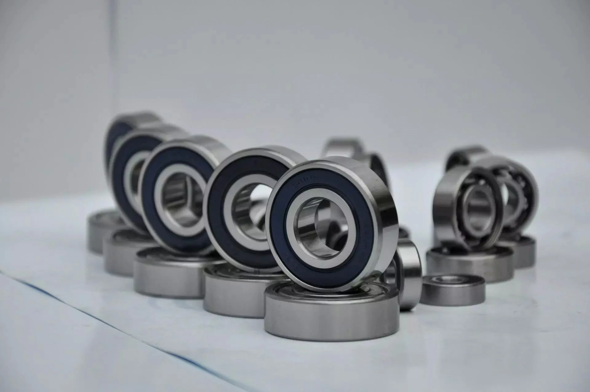
Understanding the Different Types of Bearings
When you are looking for a bearing, you have many options to choose from. This article will explain the various types, functions, and working principles of different types of bearings. Once you understand the basic components, you can make an informed decision about which 1 to buy. Here’s an overview of some of the most common types. Learn more about each type below! Read on to learn about the differences between these different types of bearings! Posted in Articles
Functions
Bearings serve as an integral part of a mechanical device. These devices help transfer torque from 1 part of a structure to another. These mechanisms increase the efficiency of a shaft by increasing its life. However, the functions of bearings depend on the application of the structure. Among other functions, bearings provide support to shafts. Anti-friction bearings come in 2 types: ball and roller bearings. These components have line and point contact, which is the most common type. Archimedes’s principle states that the force is equal to the weight of the fluid that is being displaced. Bearings can transfer lateral loads to a substructure.
A bearing has 2 primary functions. The first is to prevent direct metal-to-metal contact. A bearing prevents friction, heat generation, and wear and tear of components. A bearing also reduces energy consumption. Its other purpose is to guide and support a rotating body. In addition to these functions, bearings can also reduce wear and tear on a machine. As a result, they are among the most widely used machines in the world.
Seals are a major component of a bearing. They prevent foreign materials from entering and lubricating the moving parts. The design of seal lips determines their effectiveness. Fuel economy regulations and CO2 emissions regulations are pushing the demand for low-friction bearings. However, high-performance seals do not always provide high-performance. As a result, current estimations of the friction in bearings depend on trial and error methods.
Another important function of bearings is that they transfer the load of a rotating component to its housing. This load can be axial or radial. Bearings also limit movement to predefined directions. Some types of rolling element bearings have balls or cylinders inside. These bearings are less frictional than sliding ones, thus they allow parts to move freely during rotation. These parts can then be used for various applications. So, bearings are an integral part of machines.
Types
The most common type of bearing is a plain bearing. It uses surfaces in rubbing contact to transmit movement from 1 part to another. These bearings may be discrete or may consist of a hole in a metal sleeve or a planar surface bearing another part. Some plain bearings are flanged, while others are made of a sleeve with a flange at 1 end. These bearings often give acceptable accuracy and life, but they are expensive and cannot be used in large scale applications.
Radial bearings are used when there is a need for high-speed or corrosive parts. This type of bearing also serves as a support in an intermediate situation. Its 2 components are called the base and the cover. The base and cover are connected and are arranged parallel to the main axis. This type of bearing is used in steady-state and axial motion applications. The radial bearings are also used when the shafts are long.
Angular contact bearings are another type of bearing. These are easy to install and require minimal maintenance. Their races are displaced along the axis. They are also better at handling axial loads and transferring them to the housing. These types of bearings are commonly used in pumps, automobiles, and high-speed applications. If you are looking for an affordable, reliable bearing, look no further than the angular contact bearing.
Another type of bearing is a self-lubricating bushing. These are lightweight and wear-resistant. Unlike the other types of bearing, they do not require any lubrication or maintenance. In fact, some are completely maintenance-free. But if you’re worried about maintenance, this type of bearing may be a good choice. There are many benefits of using self-lubricating bushings. It is also a good option for applications where your machine is exposed to extreme temperatures.
Working principle
A bearing has 2 primary functions: support and load transfer. In engineering applications, the bearing tends to push the load in the direction of the shaft. A radial load pushes the bearing downward and a thrust load pushes it sideways. Both types of load transfer are important in a variety of applications. The working principle of each type is described below. Listed below are the main uses for each type of bearing.
A plain bearing uses a PTFE liner on the interface of 2 moving parts. The PTFE liner acts as a lubricant and may be filtered to alter its friction. The journal bearing uses the motion of the journal to force fluid into the gap between 2 moving parts. This results in a small amount of play in the bearing. This play is acceptable for most applications. A ball bearing may have a maximum play of 2 mm for a ten-millimeter shaft.
The primary function of a bearing is to assist in rotation and to reduce mechanical friction between the 2 objects. A bearing may be installed as a separate device or as an integral part of a machine. For more complex applications, bearings are very precise components requiring the highest standards of technology. For this reason, it is important to understand the working principle of bearings. The next time you need to lift or slide a heavy object, consider a bearing.
Ball bearings are a common type of ball bearing and can be found in industrial machinery and automobiles. Their unique structure helps them support less weight. This is because they are comprised of 2 rings – an inner race and an outer race. The balls themselves have a small area of contact and transfer axial loads in 1 direction. A cage surrounds the balls and prevents them from colliding. This makes ball bearings a popular choice for many applications.
Sealing system
A bearing’s seals are vital for the operation of rolling and rotating components. These systems enable rotation and linear movement while limiting friction and dispersing stress. Without the proper seals, these components could face catastrophic failure. In addition to protecting the bearing from external forces, seals help retain lubricant inside the system and prevent harmful particles from entering the gap. A seal’s lubrication helps prevent the onset of mechanical damage and prolongs the life of the bearing.
A bearing seal is made up of 2 parts: the inner sealing element and the outer sealing element. A passageway runs through the bearing assembly to the outer seal element. A hydraulic press or pneumatic jack is recommended for installing the seal. These tools are effective in reducing deformation and improving seal installation quality. When fitting the seal, ensure that the tool does not hit the seal directly. A proper adopter will distribute the load uniformly across the seal.
The seal’s efficiency depends on its gap. A four-inch shaft seal can flow 0.5 standard cubic feet per minute. A seal’s efficiency is highly dependent on the gap size. The gap size is a cube of the flow through the system. A smaller gap size allows high flow and pressure but less leakage. If both surfaces of the seal have similar pressures and flow rates, the seal is efficient. However, a small gap reduces the pressures and reduces wear.
Mechanical seals have numerous advantages, including their ability to protect against contaminants and splashing liquids. Labyrinth seals are the first line of defense against leaks. They operate without friction. Their high level of sealing efficiency helps ensure that the bearing remains operational for long. This type of seal is made from metal plates and is designed for a wide temperature range and misalignment. Its advantages include being easy to install and offering 100% sealing efficiency.
Maintenance
Bearing maintenance is critical to ensuring that your bearings keep operating at their peak performance. Proper maintenance will improve bearing life, reduce downtime and increase productivity while reducing costs. Here is an 8-point checklist to optimize your bearings and make them last longer. To optimize their performance, you should follow these steps regularly. In case a bearing does not last long, you should replace it as soon as possible. Listed below are some tips to ensure proper maintenance.
The first step is to determine how often your bearings require lubrication. Some manufacturers recommend that you lubricate them weekly, but this can do more harm than good. Instead, use ultrasound to measure the level of friction and trend its levels. This way, you will know exactly when to grease your bearings. It’s also important to check how often they should be inspected and calibrated. A professional can provide guidance on proper maintenance.
Next, inspect your bearings for cracks and scratches. You should never install a bearing that has been dropped or scratched. Even a small crack will affect the performance of the bearing and could lead to its premature failure. A proper alignment is essential for the bearing to function properly. Make sure you have the correct tools to perform this task. These tools can help you reduce manual work and promote safe bearing maintenance. You should also ensure that the shaft and housing are clean and undamaged.
Proper maintenance can prolong bearing service life. Proper lubrication, mounting, inspection, basic condition monitoring, and dismounting can extend their life. Proper maintenance extends their lifespan and improves plant productivity. While bearings are essential for machinery, you should make sure you follow the proper safety procedures every time you work with them. These tips will also help prevent accidents and maintain your machine’s efficiency. Once you’ve followed these guidelines, you can safely inspect your bearings and ensure that they’re operating at their optimum capacity.
China Standard Hydraulic Breaker Hammer Cylinder Hanwoo Rhb305, Rhb313, Rhb321, Rhb322/325/323, Rhb340 near me factory
Product Description
We are manufacturer of hydraulic breakers/hammers and replacement spare parts for hydraulic breakers of Soosan, Hanwoo,NPK,Toyo,Furukawa, montabert, rammer, atlas copco, MSB etc., The hydraulic breaker parts we have are: front head, back head, cylinder, chisel tool, seal kits ,piston, diaphragm, thrust bush, ring bush, front cover ,rod pin/chisel pin, stop pin, accumulator, through bolt, side bolt , bracket, upper cushion, lower cushion ,damper etc.
we can also make and install excavator hydraulic kits/hammer lines/piping kits/hydraulic installation kits/breaker lines for hydraulic hammer, hydraulic shear, hydraulic crusher, quick coupler, demolition grab, power rammer etc. We can also supply other excavator parts.
We can produce more than 1000 types of chisels for hydraulic breakers for most world famous hydraulic breakers tool diameter vary from 40mm to 200mm. the following are part of the models that we can produce hydraulic hammer chisel tools for:
| Krupp | HM45,HM50/55,HM60/75,HM85,HM130/135,HM170/185,HM200,HM300/301/305,HM400/401,HM550/560CS,HM580,HM600/601 |
| HM700/702/705,HM710/720CS,HM800,HM900/901/902,HM950/960CS,HM1200,HM1300/1500CS,HM1800/2000CS,HM2200/2500CS | |
| RAMMER | S21,S20/22,S23/D30,S24,S25,S26,S29,S52,S54/D60,S55,S56/D70,S82,S83/D110,S84,S86,ROX100,ROX400,ROX700, |
| E64,E66,E68,G80,G100,G120 | |
| N.P.K | H08X,H1XA,H2XA,H3XA,H4X,MB5X/6X,H7X,H8XA,H9X,H10X,H10XB/10XE,H11X/14X,H12X,H16X,H20X/20XE,H12X/E212,H18X/E218 |
| INDECO | MES350,HB5,MES553,MES621,MES1200,HB12,HB19,MES1800,HB27,MES2500 |
| MONTABERT | BRH30,BRH40,BRH45,BRH60,BRH76/91,BRP100,BRP130,BRP125,BRH250, |
| RH501,BRH620, BRH625,BRH750,BRV32 | |
| STANLEY | MB125,MB250/350,MB550,MB800/875,MB1500/1550,MB1950/1875,MB3950,MB30EX,MB40EX |
| FURUKAWA | HB05R,HB1G,HB2G,HB3G,HB5G,HB8G,HB10G,HB15G,HB20G,HB30G,HB40G,HB50G, |
| F-1,F-2,F-3,F-4,F-5,F-6,F-9,F-12,F-19,F-20,F-22,F-27,F-35,F-45,HB100,HB200,HB700 | |
| TOKU | TNB1E,TNB2E,TNB4E,TNB5E/6E,TNB7E/8E/10E,TNB13E,TNB14E/16E,TNB22E |
| OKADA | OUB301,OUB302,OUB303,OUB305,OUB308,OUB310,OUB312,OUB316,OUB318, UB8,UB11,UB14 |
| SOOSAN | SB10,SB20,SB30,SB35,SB40,SB43,SB45,SB50,SB60,SB70,SB81,SB81NSB100,SB121,SB130,SB151 |
| SH200,SH400,SH700,SH18G,SH20G,SH30G,SH35G,SH40G,SH50G | |
| KWANGLIM | SG200,SG300,KSG350,SG400,SG600,SG800,SG1200,SG1800,SG2100,SG2500, |
| DAEMO | DMB03,DMB04,DMB06,DMB4000,DMB5000,S150-V,S500-V,S900-V,S1300-V,S1800-V,S2200-1,S2200-2,S2500,S3000/3600/4500 |
| HANWOO | RHB301,RHB302,RHB303,RHB304,RHB305,RHB306,RHB308,RHB309,RHB313, RHB322,RHB328/332 |
| DAINONG | D30,D50,D60,D70/90,D110,D130,D160,T180,K20 |
| K25,K30,K50,K80,K120,K55S,K40S, | |
| ATLASCOPCO | TEX75/80/100H/HS,TEX110H/HS,TEX180H/HS,TEX250H1,TEX400H/HS,TEX600/700/900H/HS,TEX1400H/HS,TEX1800/2000H/HS |
| GB | GB1T,GB2T,GB3T,GB4T,GB5T,GB6T,GB8T,GB8AT,GB11T,GB14T,GB170E,GB220E,GB290E/300E,GB400E |
| TOYO | THBB71,THBB101,THBB301,THBB401,THBB801,THBB1400,THBB2000 |
FAQ
Q: Are you a manufacturer?
A: Yes,our factory was established in 2571.
Q: Are you sure your product will fit my excavator?
A: Our equipments are suitable for most excavators. Show us your excavator model, we’ll confirm the solution.
Q: Can you produce according to customers’ design?
A: Sure, OEM/ODM service available. We are professional manufacturer in HangZhou.
Q: What’s the MOQ and payment terms?
A: MOQ is 1set. Payment via T/T,L/C, Western Union accepted, other terms can be negotiated.
Q: How about delivery time?
A: 5-25 work days after the payment.
Q: How about the package?
A: Our equipments wrapped by stretch film, packed by pallet or polywood case; or as requested.
Q: Which country have you exported?
A: Saudi Arabia, America, Thailand, Cyprus, India, Canada, Australia, Peru, Egypt, Brazil, Mexico, Iran, South Africa, etc.
Should you have any questions,call me,let’s talk details.
What Are Worm Gears and Worm Shafts?
If you’re looking for a fishing reel with a worm gear system, you’ve probably come across the term ‘worm gear’. But what are worm gears and worm shafts? And what are the advantages and disadvantages of worm gears? Let’s take a closer look! Read on to learn more about worm gears and shafts! Then you’ll be well on your way to purchasing a reel with a worm gear system.
worm gear reducers
Worm shaft reducers have a number of advantages over conventional gear reduction mechanisms. First, they’re highly efficient. While single stage worm reducers have a maximum reduction ratio of about 5 to 60, hypoid gears can typically go up to a maximum of 1 hundred and 20 times. A worm shaft reducer is only as efficient as the gearing it utilizes. This article will discuss some of the advantages of using a hypoid gear set, and how it can benefit your business.
To assemble a worm shaft reducer, first remove the flange from the motor. Then, remove the output bearing carrier and output gear assembly. Lastly, install the intermediate worm assembly through the bore opposite to the attachment housing. Once installed, you should carefully remove the bearing carrier and the gear assembly from the motor. Don’t forget to remove the oil seal from the housing and motor flange. During this process, you must use a small hammer to tap around the face of the plug near the outside diameter of the housing.
Worm gears are often used in reversing prevention systems. The backlash of a worm gear can increase with wear. However, a duplex worm gear was designed to address this problem. This type of gear requires a smaller backlash but is still highly precise. It uses different leads for the opposing tooth face, which continuously alters its tooth thickness. Worm gears can also be adjusted axially.
worm gears
There are a couple of different types of lubricants that are used in worm gears. The first, polyalkylene glycols, are used in cases where high temperature is not a concern. This type of lubricant does not contain any waxes, which makes it an excellent choice in low-temperature applications. However, these lubricants are not compatible with mineral oils or some types of paints and seals. Worm gears typically feature a steel worm and a brass wheel. The brass wheel is much easier to remodel than steel and is generally modeled as a sacrificial component.
The worm gear is most effective when it is used in small and compact applications. Worm gears can greatly increase torque or reduce speed, and they are often used where space is an issue. Worm gears are among the smoothest and quietest gear systems on the market, and their meshing effectiveness is excellent. However, the worm gear requires high-quality manufacturing to perform at its highest levels. If you’re considering a worm gear for a project, it’s important to make sure that you find a manufacturer with a long and high quality reputation.
The pitch diameters of both worm and pinion gears must match. The 2 worm cylinders in a worm wheel have the same pitch diameter. The worm wheel shaft has 2 pitch cylinders and 2 threads. They are similar in pitch diameter, but have different advancing angles. A self-locking worm gear, also known as a wormwheel, is usually self-locking. Moreover, self-locking worm gears are easy to install.
worm shafts
The deflection of worm shafts varies with toothing parameters. In addition to toothing length, worm gear size and pressure angle, worm gear size and number of helical threads are all influencing factors. These variations are modeled in the standard ISO/TS 14521 reference gear. This table shows the variations in each parameter. The ID indicates the worm shaft’s center distance. In addition, a new calculation method is presented for determining the equivalent bending diameter of the worm.
The deflection of worm shafts is investigated using a four-stage process. First, the finite element method is used to compute the deflection of a worm shaft. Then, the worm shaft is experimentally tested, comparing the results with the corresponding simulations. The final stage of the simulation is to consider the toothing geometry of 15 different worm gear toothings. The results of this step confirm the modeled results.
The lead on the right and left tooth surfaces of worms is the same. However, the lead can be varied along the worm shaft. This is called dual lead worm gear, and is used to eliminate play in the main worm gear of hobbing machines. The pitch diameters of worm modules are equal. The same principle applies to their pitch diameters. Generally, the lead angle increases as the number of threads decreases. Hence, the larger the lead angle, the less self-locking it becomes.
worm gears in fishing reels
Fishing reels usually include worm shafts as a part of the construction. Worm shafts in fishing reels allow for uniform worm winding. The worm shaft is attached to a bearing on the rear wall of the reel unit through a hole. The worm shaft’s front end is supported by a concave hole in the front of the reel unit. A conventional fishing reel may also have a worm shaft attached to the sidewall.
The gear support portion 29 supports the rear end of the pinion gear 12. It is a thick rib that protrudes from the lid portion 2 b. It is mounted on a bushing 14 b, which has a through hole through which the worm shaft 20 passes. This worm gear supports the worm. There are 2 types of worm gears available for fishing reels. The 2 types of worm gears may have different number of teeth or they may be the same.
Typical worm shafts are made of stainless steel. Stainless steel worm shafts are especially corrosion-resistant and durable. Worm shafts are used on spinning reels, spin-casting reels, and in many electrical tools. A worm shaft can be reversible, but it is not entirely reliable. There are numerous benefits of worm shafts in fishing reels. These fishing reels also feature a line winder or level winder.
worm gears in electrical tools
Worms have different tooth shapes that can help increase the load carrying capacity of a worm gear. Different tooth shapes can be used with circular or secondary curve cross sections. The pitch point of the cross section is the boundary for this type of mesh. The mesh can be either positive or negative depending on the desired torque. Worm teeth can also be inspected by measuring them over pins. In many cases, the lead thickness of a worm can be adjusted using a gear tooth caliper.
The worm shaft is fixed to the lower case section 8 via a rubber bush 13. The worm wheel 3 is attached to the joint shaft 12. The worm 2 is coaxially attached to the shaft end section 12a. This joint shaft connects to a swing arm and rotates the worm wheel 3.
The backlash of a worm gear may be increased if the worm is not mounted properly. To fix the problem, manufacturers have developed duplex worm gears, which are suitable for small backlash applications. Duplex worm gears utilize different leads on each tooth face for continuous change in tooth thickness. In this way, the center distance of the worm gear can be adjusted without changing the worm’s design.
worm gears in engines
Using worm shafts in engines has a few benefits. First of all, worm gears are quiet. The gear and worm face move in opposite directions so the energy transferred is linear. Worm gears are popular in applications where torque is important, such as elevators and lifts. Worm gears also have the advantage of being made from soft materials, making them easy to lubricate and to use in applications where noise is a concern.
Lubricants are necessary for worm gears. The viscosity of lubricants determines whether the worm is able to touch the gear or wheel. Common lubricants are ISO 680 and 460, but higher viscosity oil is not uncommon. It is essential to use the right lubricants for worm gears, since they cannot be lubricated indefinitely.
Worm gears are not recommended for engines due to their limited performance. The worm gear’s spiral motion causes a significant reduction in space, but this requires a high amount of lubrication. Worm gears are susceptible to breaking down because of the stress placed on them. Moreover, their limited speed can cause significant damage to the gearbox, so careful maintenance is essential. To make sure worm gears remain in top condition, you should inspect and clean them regularly.
Methods for manufacturing worm shafts
A novel approach to manufacturing worm shafts and gearboxes is provided by the methods of the present invention. Aspects of the technique involve manufacturing the worm shaft from a common worm shaft blank having a defined outer diameter and axial pitch. The worm shaft blank is then adapted to the desired gear ratio, resulting in a gearbox family with multiple gear ratios. The preferred method for manufacturing worm shafts and gearboxes is outlined below.
A worm shaft assembly process may involve establishing an axial pitch for a given frame size and reduction ratio. A single worm shaft blank typically has an outer diameter of 100 millimeters, which is the measurement of the worm gear set’s center distance. Upon completion of the assembly process, the worm shaft has the desired axial pitch. Methods for manufacturing worm shafts include the following:
For the design of the worm gear, a high degree of conformity is required. Worm gears are classified as a screw pair in the lower pairs. Worm gears have high relative sliding, which is advantageous when comparing them to other types of gears. Worm gears require good surface finish and rigid positioning. Worm gear lubrication usually comprises surface active additives such as silica or phosphor-bronze. Worm gear lubricants are often mixed. The lubricant film that forms on the gear teeth has little impact on wear and is generally a good lubricant.
China factory Daemo Hydraulic Hammer Cylinder with Durable Quality From China Factory with Great quality
Product Description
ARE YOU LOOKING FOR A RELIABLE FACTORY FOR HYDRAULIC BREAKER SPARE PARTS WITH
STABLE QUALITY & AFTER-SALES SERVICE GUARANTEES?
DO YOU HAVE CLIENTS WHO WANT TO BUY THE DURABLE LONG LIFETIME & HIGH-END FINISH
HYDRAULIC HAMMER SPARE PARTS AS JAPAN OR KOREA’S?
ARE YOU FINDING JAPAN/KOREA SUPPLIERS’ OFFER SO HIGH AND THINK ABOUT
A BETTER ECONOMIC ALTERNATIVE?
HOW ABOUT A PERSON HELP YOU TO SOLVE ALL THE PROBLEMS AND LEAVE YOU
TO SIT BACK AND RELAX?
Hi, I am Ryan, I have 8 years of international trade sales experience and now working for
HangZhou Zhongye Machinery Manufacture Co., Ltd.
I know you are looking for high-quality SPARE PARTS while affordable like this:
Now you can stop searching and comparison, I bet our factory can be your best choice. WHY?
1, Stable quality in various actual fields worldwide
Our chisels have been supplied to over 70 companies of more than 30 countries
Certificate such as CE, ISO, can also be a proof of our quality.
2, Well equipped production facility.
The one-stop operational resource that covers 2 manufacturing factories for hydraulic breaker, chisel,
and spare parts which 10 years’ history Zhongye machinery factory for mid-range products.
Second NEW factory with an up-to-date production facility for high-end hydraulic breaker, chisel, and spare parts;
Third, We have CYLINDER for the following hydraulic breaker/hammers:
you can also send us your drawing for mass customized production.
| Brand Name |
Below models are part of hydraulic breaker models for your refference. |
| Soosan | SB40 SB43 SB45 SB50 SB60 SB81N SB81 SB81A SB100 SB121 SB130 SB140 SB151 |
| Furukawa | HB20G HB30G HB40G HB8G HB10G HB5G HB15G F19 F20 F22 F35 F70 FX47 F45 FS37 F27 FS22 F27 F12 F9 F6 |
| Toku | TNB150 TNB151 TNB14E TNB5M TNB4E TNB6E TNB7E TNB14B TNB14 TNB190 TNB230 |
| General | GB8AT GB8T GB8F GB2T GB5T GB4T GB6T GB540E GB580E |
| NPK | H2X NPK H4X NPK H6X NPK H-7X NPK H-9X NPK H-10X H-10XB E-12X E210A/B NPK NPK H12XB NPK H14X NPK H20X |
| Daemo | S2100 S2200 S2300 S3000 |
| Krup | HM960 HM951 HM720 HM980 HM1000 HM1500 |
| MSB | MS600 Xihu (West Lake) Dis.350 |
| Okada | OUB308 OUB312 OUB316 |
| Toy | THBB401 THBB801 THBB1600 THBB2000 |
| Hanwoo | RHB323 RHB313 RHB305 RHB325 RHB326 RHB328 RHB330 RHB340 RHB350 |
3, Years of accumulated Art-Heat Treatment Technology
10 years of accumulated heat treatment technology, making the our spare parts 2 TIMES durable than most small workshops.
4, Quality Assurance
Every working procedure would influence the product quality, thus each working procedure should
sustaining testing on our production lines. Our warranty policy could make you rest easy.
5, After-sales service
With my 8 years’ export experience, I was confident I could ensure the smooth process from order
receiving until the order arrives at your hand.
Hence, Zhongye is available to show you our product range and CZPT you in the choice of the products that best fit your needs,
Isn’t good enough?
I have a trade secret can make your business more profitable and competitive.
I guess most of your competitors haven’t known that,
Just send me your detailed inquiry at the bottom and I will share it with you for free.
Grab the opportunity today! or your competitors may have learned that.
The benefits of rubber bushings and how they work
If you have experienced increased vibration while driving, you know the importance of replacing the control arm bushings. The resulting metal-to-metal contact can cause annoying driving problems and be a threat to your safety. Over time, the control arm bushings begin to wear out, a process that can be exacerbated by harsh driving conditions and environmental factors. Additionally, larger tires that are more susceptible to bushing wear are also prone to increased vibration transfer, especially for vehicles with shorter sidewalls. Additionally, these plus-sized tires, which are designed to fit on larger rims, have a higher risk of transmitting vibrations through the bushings.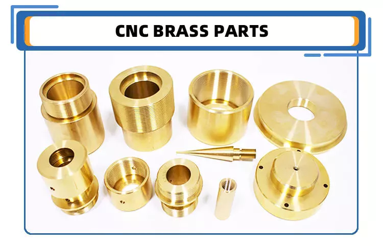
rubber
Rubber bushings are rubber tubes that are glued into the inner or outer curve of a cylindrical metal part. The rubber is made of polyurethane and is usually prestressed to avoid breaking during installation. In some cases, the material is also elastic, so it can slide. These properties make rubber bushings an integral part of a vehicle’s suspension system. Here are some benefits of rubber bushings and how they work.
Rubber bushings are used to isolate and reduce vibration caused by the movement of the 2 pieces of equipment. They are usually placed between 2 pieces of machinery, such as gears or balls. By preventing vibrations, rubber bushings improve machine function and service life. In addition to improving the overall performance of the machine, the rubber bushing reduces noise and protects the operator from injury. The rubber on the shock absorber also acts as a vibration isolator. It suppresses the energy produced when the 2 parts of the machine interact. They allow a small amount of movement but minimize vibration.
Both rubber and polyurethane bushings have their advantages and disadvantages. The former is the cheapest, but not as durable as polyurethane. Compared to polyurethane, rubber bushings are a better choice for daily commutes, especially long commutes. Polyurethane bushings provide better steering control and road feel than rubber, but can be more expensive than the former. So how do you choose between polyurethane and rubber bushings?
Polyurethane
Unlike rubber, polyurethane bushings resist high stress environments and normal cycling. This makes them an excellent choice for performance builds. However, there are some disadvantages to using polyurethane bushings. Read on to learn about the advantages and disadvantages of polyurethane bushings in suspension applications. Also, see if a polyurethane bushing is suitable for your vehicle.
Choosing the right bushing for your needs depends entirely on your budget and application. Softer bushings have the lowest performance but may have the lowest NVH. Polyurethane bushings, on the other hand, may be more articulated, but less articulated. Depending on your needs, you can choose a combination of features and tradeoffs. While these are good options for everyday use, for racing and hardcore handling applications, a softer option may be a better choice.
The initial hardness of the polyurethane bushing is higher than that of the rubber bushing. The difference between the 2 materials is determined by durometer testing. Polyurethane has a higher hardness than rubber because it does not react to load in the same way. The harder the rubber, the less elastic, and the higher the tear. This makes it an excellent choice for bushings in a variety of applications.
hard
Solid bushings replace the standard bushings on the subframe, eliminating axle clutter. New bushings raise the subframe by 0.59″ (15mm), correcting the roll center. Plus, they don’t create cabin noise. So you can install these bushings even when your vehicle is lowered. But you should consider some facts when installing solid casing. Read on to learn more about these casings.
The stiffest bushing material currently available is solid aluminum. This material hardly absorbs vibrations, but it is not recommended for everyday use. Its stiffness makes it ideal for rail vehicles. The aluminum housing is prone to wear and tear and may not be suitable for street use. However, the solid aluminum bushings provide the stiffest feel and chassis feedback. However, if you want the best performance in everyday driving, you should choose a polyurethane bushing. They have lower friction properties and eliminate binding.
Sturdy subframe bushings will provide more driver feedback. Additionally, it will strengthen the rear body, eliminating any movement caused by the subframe. You can see this structural integration on the M3 and M4 models. The benefits of solid subframe bushings are numerous. They will improve rear-end handling without compromising drivability. So if you plan to install a solid subframe bushing, be sure to choose a solid bushing.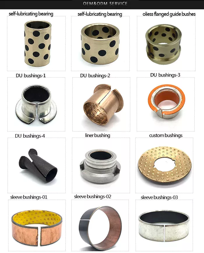
Capacitor classification
In the circuit, there is a high electric field on both sides of the capacitor grading bushing. This is due to their capacitor cores. The dielectric properties of the primary insulating layer have a great influence on the electric field distribution within the bushing. This article discusses the advantages and disadvantages of capacitor grade bushings. This article discusses the advantages and disadvantages of grading bushings for capacitors in DC power systems.
One disadvantage of capacitor grading bushings is that they are not suitable for higher voltages. Capacitor grading bushings are prone to serious heating problems. This may reduce their long-term reliability. The main disadvantage of capacitor grading bushings is that they increase the radial thermal gradient of the main insulation. This can lead to dielectric breakdown.
Capacitor grading bushing adopts cylindrical structure, which can suppress the influence of temperature on electric field distribution. This reduces the coefficient of inhomogeneity of the electric field in the confinement layer. Capacitor grading bushings have a uniform electric field distribution across their primary insulation. Capacitive graded bushings are also more reliable than nonlinear bushings.
Electric field variation is the most important cause of failure. The electrode extension layer can be patterned to control the electric field to avoid flashover or partial discharge of the primary insulating material. This design can be incorporated into capacitor grading bushings to provide better electric fields in high voltage applications. This type of bushing is suitable for a wide range of applications. This article discusses the advantages and disadvantages of capacitor grade bushings.
Metal
When choosing between plastic and metal sleeves, it is important to choose a product that can handle the required load. Plastic bushings tend to deteriorate and often crack under heavy loads, reducing their mechanical strength and service life. Metal bushings, on the other hand, conduct heat more efficiently, preventing any damage to the mating surfaces. Plastic bushings can also be made with lubricating fillers added to a resin matrix.
Plastic bushings have many advantages over metal bushings, including being cheap and versatile. Plastic bushings are now used in many industries because they are inexpensive and quick to install. These plastic products are also self-lubricating and require less maintenance than metals. They are often used in applications where maintenance costs are high or parts are difficult to access. Also, if they are prone to wear and tear, they are easy to replace.
Metal bushings can be made of PTFE, plastic or bronze and are self-lubricating. Graphite plugs are also available for some metal bushings. Their high load capacity and excellent fatigue resistance make them a popular choice for automotive applications. The bi-metallic sintered bronze layer in these products provides excellent load-carrying capacity and good friction properties. The steel backing also helps reduce processing time and avoids the need for additional pre-lubrication.
plastic
A plastic bushing is a small ball of material that is screwed onto a nut or locknut on a mechanical assembly. Plastic bushings are very durable and have a low coefficient of friction, making them a better choice for durable parts. Since they do not require lubrication, they last longer and cost less than their metal counterparts. Unlike metal bushings, plastic bushings also don’t scratch or attract dirt.
One type of acetal sleeve is called SF-2. It is made of metal alloy, cold rolled steel and bronze spherical powder. A small amount of surface plastic penetrated into the voids of the copper spherical powder. Plastic bushings are available in a variety of colors, depending on the intended application. SF-2 is available in black or grey RAL 7040. Its d1 diameter is sufficient for most applications.
Another acetal sleeve is UHMW-PE. This material is used in the production of bearings and in low load applications. This material can withstand pressures from 500 to 800 PSI and is widely available. It is also self-lubricating and readily available. Due to its high resistance to temperature and chemical agents, it is an excellent choice for low-load industrial applications. If you’re in the market for an alternative to nylon, consider acetal.
Positional tolerances in many automotive components can cause misalignment. Misaligned plastic bushings can negatively impact the driver’s experience. For example, the cross tubes used to mount the seat to the frame are made by a stamping process. The result is a misalignment that can increase torque. Also, the plastic bushing is pushed to 1 side of the shaft. The increased pressure results in higher friction, which ultimately results in a poor driving experience.
v