Product Description
DOT/CE/BV/ISO/SGS/TPED approval 2L/5L/7L/8L/10/14L/20L portable gas cylinders fill with oxygen gas, argon gas, co2 gas, helium gas, mixture gases ,etc.
| Type | (mm) Outside Diameter |
(L) Water Capacity |
(mm) () Height (Withoutvalve) |
(Kg) (,) Weight(Without valve,cap) |
(Mpa) Working Pressure |
(mm) Design Wall Thickness |
Material Grades |
| ISO102-1.8-150 | 102 | 1.8 | 325 | 3.5 | 150 | 3 | 37Mn |
| ISO102-3-150 | 3 | 498 | 5.2 | ||||
| ISO102-3.4-150 | 3.4 | 555 | 5.7 | ||||
| ISO102-4.4-150 | 4.4 | 700 | 7.2 | ||||
| ISO108-1.4-150 | 108 | 1.4 | 240 | 2.9 | 150 | 3.2 | 37Mn |
| ISO108-1.8-150 | 1.8 | 285 | 3.3 | ||||
| ISO108-2-150 | 2 | 310 | 3.6 | ||||
| ISO108-3-150 | 3 | 437 | 4.9 | ||||
| ISO108-3.6-150 | 3.6 | 515 | 5.7 | ||||
| ISO108-4-150 | 4 | 565 | 6.2 | ||||
| ISO108-5-150 | 5 | 692 | 7.5 | ||||
| ISO140-3.4-150 | 140 | 3.4 | 321 | 5.8 | 150 | 4.1 | 37Mn |
| ISO140-4-150 | 4 | 365 | 6.4 | ||||
| ISO140-5-150 | 5 | 440 | 7.6 | ||||
| ISO140-6-150 | 6 | 515 | 8.8 | ||||
| ISO140-6.3-150 | 6.3 | 545 | 9.2 | ||||
| ISO140-6.7-150 | 6.7 | 567 | 9.5 | ||||
| ISO140-7-150 | 7 | 595 | 9.9 | ||||
| ISO140-7.5-150 | 7.5 | 632 | 10.5 | ||||
| ISO140-8-150 | 8 | 665 | 11 | ||||
| ISO140-9-150 | 9 | 745 | 12.2 | ||||
| ISO140-10-150 | 10 | 830 | 13.5 | ||||
| ISO140-11-150 | 11 | 885 | 14.3 | ||||
| ISO140-13.4-150 | 13.4 | 1070 | 17.1 | ||||
| ISO140-14-150 | 14 | 1115 | 17.7 | ||||
| ISO159-7-150 | 159 | 7 | 495 | 9.8 | 150 | 4.7 | 37Mn |
| ISO159-8-150 | 8 | 554 | 10.8 | ||||
| ISO159-9-150 | 9 | 610 | 11.7 | ||||
| ISO159-10-150 | 10 | 665 | 12.7 | ||||
| ISO159-11-150 | 11 | 722 | 13.7 | ||||
| ISO159-12-150 | 12 | 790 | 14.8 | ||||
| ISO159-12.5-150 | 12.5 | 802 | 15 | ||||
| ISO159-13-150 | 13 | 833 | 15.6 | ||||
| ISO159-13.4-150 | 13.4 | 855 | 16 | ||||
| ISO159-13.7-150 | 13.7 | 878 | 16.3 | ||||
| ISO159-14-150 | 14 | 890 | 16.5 | ||||
| ISO159-15-150 | 15 | 945 | 17.5 | ||||
| ISO159-16-150 | 16 | 1000 | 18.4 | ||||
| ISO180-8-150 | 180 | 8 | 480 | 13.8 | 150 | 5.3 | 37Mn |
| ISO180-10-150 | 10 | 570 | 16.1 | ||||
| ISO180-12-150 | 12 | 660 | 18.3 | ||||
| ISO180-15-150 | 15 | 790 | 21.6 | ||||
| ISO180-20-150 | 20 | 1015 | 27.2 | ||||
| ISO180-21-150 | 21 | 1061 | 28.3 | ||||
| ISO180-21.6-150 | 21.6 | 1087 | 29 | ||||
| ISO180-22.3-150 | 22.3 | 1100 | 29.4 | ||||
| ISO219-20-150 | 219 | 20 | 705 | 27.8 | 150 | 6.1 | 37Mn |
| ISO219-25-150 | 25 | 855 | 32.8 | ||||
| ISO219-27-150 | 27 | 915 | 34.8 | ||||
| ISO219-36-150 | 36 | 1185 | 43.9 | ||||
| ISO219-38-150 | 38 | 1245 | 45.9 | ||||
| ISO219-40-150 | 40 | 1305 | 47.8 | ||||
| ISO219-45-150 | 45 | 1455 | 52.9 | ||||
| ISO219-46.7-150 | 46.7 | 1505 | 54.6 | ||||
| ISO219-50-150 | 50 | 1605 | 57.9 |
| RECORD OF HYDROSTATIC TESTS ON CYLINDERS Time≥ 60S | ||||||||
| S.N | Serial No. | The weight without valve&cap(kg) | Volumetric Capacity(L) | Total expansion(ml) | Permanent expansion(ml) | Percent of Permanent to totalexpanison(%) | Test Pressure 250Bar | Lot and Batch No. |
| 1 | 20T164001 | 18 | 14.2 | 74.1 | 0.9 | 1.2 | 25 | T09 |
| 2 | 20T164002 | 17.8 | 14.3 | 69.0 | 1 | 1.4 | 25 | T09 |
| 3 | 20T164003 | 17.9 | 14.2 | 74.1 | 1 | 1.4 | 25 | T09 |
| 4 | 20T164004 | 17.7 | 14.3 | 70.9 | 0.9 | 1.3 | 25 | T09 |
| 5 | 20T164005 | 18.2 | 14.3 | 69.0 | 0.9 | 1.3 | 25 | T09 |
| 6 | 20T164006 | 17.6 | 14.2 | 70.1 | 0.9 | 1.3 | 25 | T09 |
| 7 | 20T164007 | 18.3 | 14.2 | 71.1 | 1 | 1.4 | 25 | T09 |
| 8 | 20T164008 | 18.2 | 14.3 | 72.9 | 0.8 | 1.1 | 25 | T09 |
| 9 | 20T164009 | 17.5 | 14.3 | 69.0 | 0.9 | 1.3 | 25 | T09 |
| 10 | 20T164571 | 17.8 | 14.2 | 73.1 | 0.9 | 1.2 | 25 | T09 |
| 11 | 20T164011 | 18 | 14 | 71.4 | 1 | 1.4 | 25 | T09 |
| 12 | 20T164012 | 17.8 | 14.2 | 74.1 | 0.7 | 0.9 | 25 | T09 |
| 13 | 20T164013 | 18.6 | 14.2 | 71.1 | 1 | 1.4 | 25 | T09 |
| 14 | 20T164014 | 17.6 | 14.3 | 70.0 | 1 | 1.4 | 25 | T09 |
| 15 | 20T164015 | 17.9 | 14.1 | 72.2 | 0.8 | 1.1 | 25 | T09 |
| 16 | 20T164016 | 17.9 | 14.3 | 68.0 | 1 | 1.5 | 25 | T09 |
| 17 | 20T164017 | 18.1 | 14.2 | 74.1 | 0.8 | 1.1 | 25 | T09 |
| 18 | 20T164018 | 17.7 | 14.3 | 69.0 | 0.7 | 1.0 | 25 | T09 |
| 19 | 20T164019 | 17.7 | 14.3 | 70.0 | 0.7 | 1.0 | 25 | T09 |
| 20 | 20T164571 | 17.8 | 14.2 | 69.1 | 0.8 | 1.2 | 25 | T09 |
| 21 | 20T164571 | 17.7 | 14.3 | 72.9 | 0.7 | 1.0 | 25 | T09 |
| 22 | 20T164571 | 17.9 | 14.2 | 71.1 | 0.8 | 1.1 | 25 | T09 |
| 23 | 20T164571 | 18 | 14.2 | 69.1 | 0.7 | 1.0 | 25 | T09 |
| 24 | 20T164571 | 17.7 | 14.3 | 72.9 | 0.7 | 1.0 | 25 | T09 |
| 25 | 20T164571 | 17.8 | 14.3 | 71.9 | 1.2 | 1.7 | 25 | T09 |
| 26 | 20T164026 | 17.9 | 14.1 | 70.2 | 1 | 1.4 | 25 | T09 |
| 27 | 20T164571 | 17.8 | 14.2 | 73.1 | 0.7 | 1.0 | 25 | T09 |
| 28 | 20T164571 | 17.8 | 14.3 | 70.0 | 0.8 | 1.1 | 25 | T09 |
| 29 | 20T164571 | 17.8 | 14.2 | 71.1 | 1.2 | 1.7 | 25 | T09 |
| 30 | 20T164030 | 17.8 | 14.2 | 68.1 | 0.9 | 1.3 | 25 | T09 |
| 31 | 20T164031 | 17.7 | 14.3 | 72.9 | 0.9 | 1.2 | 25 | T09 |
| 32 | 20T164032 | 17.6 | 14.2 | 70.1 | 1 | 1.4 | 25 | T09 |
| 33 | 20T164033 | 17.8 | 14.2 | 74.1 | 1 | 1.4 | 25 | T09 |
| 34 | 20T164034 | 18 | 14 | 74.4 | 0.9 | 1.2 | 25 | T09 |
| 35 | 20T164035 | 17.8 | 14.2 | 70.1 | 0.9 | 1.3 | 25 | T09 |
| 36 | 20T164036 | 17.9 | 14.1 | 71.2 | 0.9 | 1.3 | 25 | T09 |
| 37 | 20T164037 | 17.9 | 14.3 | 70.0 | 1 | 1.4 | 25 | T09 |
| 38 | 20T164038 | 17.8 | 14.2 | 74.1 | 0.8 | 1.1 | 25 | T09 |
| 39 | 20T164039 | 17.9 | 14.1 | 71.2 | 0.9 | 1.3 | 25 | T09 |
| 40 | 20T164040 | 17.7 | 14.3 | 71.9 | 0.9 | 1.3 | 25 | T09 |
| 41 | 20T164041 | 17.8 | 14.2 | 69.1 | 1 | 1.4 | 25 | T09 |
| 42 | 20T164042 | 18 | 14.2 | 74.1 | 0.7 | 0.9 | 25 | T09 |
| 43 | 20T164043 | 18.4 | 14.2 | 71.1 | 1 | 1.4 | 25 | T09 |
| 44 | 20T164044 | 17.6 | 14.4 | 68.8 | 1 | 1.5 | 25 | T09 |
| 45 | 20T164045 | 17.8 | 14.2 | 71.1 | 0.8 | 1.1 | 25 | T09 |
| 46 | 20T164046 | 17.9 | 14.1 | 70.2 | 1 | 1.4 | 25 | T09 |
| 47 | 20T164047 | 17.8 | 14.2 | 74.1 | 0.8 | 1.1 | 25 | T09 |
| 48 | 20T164048 | 18 | 14.2 | 70.1 | 0.7 | 1.0 | 25 | T09 |
| 49 | 20T164049 | 17.9 | 14.1 | 72.2 | 0.7 | 1.0 | 25 | T09 |
| 50 | 20T164050 | 17.8 | 14.2 | 69.1 | 0.8 | 1.2 | 25 | T09 |
Q1: What is your product name?
A:hot sale ISO9809 wall thickness oxygen gas cylinder.
Q2:Where is your factory located?
A:Our factory is located in HangZhou .
Q3:How many cylinder do you produce everyday?
A: We can produce 1000 pieces everyday.
Q4: Can you provide sample?
A: Yes, we can provide you sample, but you need to pay for the sample and freight firstly.We will return the fee after you make an order.
Q5: Can you use our brand?
A: Yes, OEM is available.
| Material: | Steel |
|---|---|
| Usage: | |
| Structure: | Piston Cylinder |
| Power: | Hydraulic |
| Standard: | Standard |
| Pressure Direction: | Double-acting Cylinder |
| Customization: |
Available
|
|
|---|
What advancements in hydraulic cylinder technology have improved energy efficiency?
Advancements in hydraulic cylinder technology have led to significant improvements in energy efficiency, allowing hydraulic systems to operate more efficiently and reduce energy consumption. These advancements aim to minimize energy losses, optimize system performance, and enhance overall efficiency. Here’s a detailed explanation of some key advancements in hydraulic cylinder technology that have improved energy efficiency:
1. Efficient Hydraulic Circuit Design:
– The design of hydraulic circuits has evolved to improve energy efficiency. Advancements in circuit design techniques, such as load-sensing, pressure-compensated systems, or variable displacement pumps, help match the hydraulic power output to the actual load requirements. These designs reduce unnecessary energy consumption by adjusting the flow and pressure levels according to the system demands, rather than operating at a fixed high pressure.
2. High-Efficiency Hydraulic Fluids:
– The development of high-efficiency hydraulic fluids, such as low-viscosity or synthetic fluids, has contributed to improved energy efficiency. These fluids offer lower internal friction and reduced resistance to flow, resulting in decreased energy losses within the system. Additionally, advanced fluid additives and formulations enhance lubrication properties, reducing friction and optimizing the overall efficiency of hydraulic cylinders.
3. Advanced Sealing Technologies:
– Seal technology has advanced significantly, leading to improved energy efficiency in hydraulic cylinders. High-performance seals, such as low-friction or low-leakage seals, minimize internal leakage and friction losses. Reduced internal leakage helps maintain system pressure more effectively, resulting in less energy waste. Additionally, innovative sealing materials and designs enhance durability and extend seal life, reducing the need for frequent maintenance and replacement.
4. Electro-Hydraulic Control Systems:
– The integration of advanced electro-hydraulic control systems has greatly contributed to energy efficiency improvements. By combining electronic control with hydraulic power, these systems enable precise control over cylinder operation, optimizing energy usage. Proportional or servo valves, along with position or force feedback sensors, allow for accurate and responsive control, ensuring that hydraulic cylinders operate at the required level of performance while minimizing energy waste.
5. Energy Recovery Systems:
– Energy recovery systems, such as hydraulic accumulators, have been increasingly utilized to improve energy efficiency in hydraulic cylinder applications. Accumulators store excess energy during low-demand periods and release it when there is a peak demand, reducing the need for the hydraulic pump to provide the full power continuously. By utilizing stored energy, these systems can significantly reduce energy consumption and improve overall system efficiency.
6. Smart Monitoring and Control:
– Advancements in smart monitoring and control technologies have enabled real-time monitoring of hydraulic systems, allowing for optimized energy usage. Integrated sensors, data analytics, and control algorithms provide insights into system performance and energy consumption, enabling operators to make informed decisions and adjustments. By identifying inefficiencies or suboptimal operating conditions, energy consumption can be minimized, leading to improved energy efficiency.
7. System Integration and Optimization:
– The integration and optimization of hydraulic systems as a whole have played a significant role in improving energy efficiency. By considering the entire system layout, component sizing, and interaction between different elements, engineers can design hydraulic systems that operate in the most energy-efficient manner. Proper sizing of components, minimizing pressure drops, and reducing unnecessary piping or valve restrictions all contribute to improved energy efficiency of hydraulic cylinders.
8. Research and Development:
– Ongoing research and development efforts in the field of hydraulic cylinder technology continue to drive energy efficiency advancements. Innovations in materials, component design, system modeling, and simulation techniques help identify areas for improvement and optimize energy usage. Additionally, collaboration between industry stakeholders, research institutions, and regulatory bodies fosters the development of energy-efficient hydraulic cylinder technologies.
In summary, advancements in hydraulic cylinder technology have resulted in notable improvements in energy efficiency. Efficient hydraulic circuit designs, high-efficiency hydraulic fluids, advanced sealing technologies, electro-hydraulic control systems, energy recovery systems, smart monitoring and control, system integration and optimization, as well as ongoing research and development efforts, all contribute to reducing energy consumption and enhancing the overall energy efficiency of hydraulic cylinders. These advancements not only benefit the environment but also offer cost savings and improved performance in various hydraulic applications.
Contribution of Hydraulic Cylinders to the Efficiency of Agricultural Tasks like Plowing
Hydraulic cylinders play a significant role in enhancing the efficiency of agricultural tasks, including plowing. By providing power, control, and versatility, hydraulic cylinders enable agricultural machinery to perform tasks more effectively and with greater precision. Let’s explore how hydraulic cylinders contribute to the efficiency of plowing and other agricultural tasks:
- Powerful Force Generation: Hydraulic cylinders are capable of generating high forces, making them ideal for tasks that require substantial power, such as plowing. The hydraulic system provides pressurized fluid to the cylinders, which convert this hydraulic energy into mechanical force. This force is then utilized to drive plow blades through the soil, overcoming resistance and facilitating efficient soil penetration.
- Adjustable Working Depth: Hydraulic cylinders allow for easy and precise adjustment of plow working depth. By controlling the extension or retraction of the hydraulic cylinder, the depth of the plow blades can be adjusted according to soil conditions, crop requirements, or the farmer’s preferences. This adjustability enhances efficiency by ensuring optimal soil tillage and minimizing unnecessary energy expenditure.
- Responsive Control: Hydraulic systems offer highly responsive control, enabling farmers to make quick adjustments during plowing operations. Hydraulic cylinders respond rapidly to changes in hydraulic pressure and valve settings, allowing for immediate modifications in the plow’s position, depth, or angle. This responsiveness enhances efficiency by facilitating on-the-go adjustments based on soil variations, obstacles, or changing field conditions.
- Implement Versatility: Hydraulic cylinders enable the attachment of various implements to agricultural machinery, expanding their functionality and versatility. In the case of plowing, hydraulic cylinders allow for the attachment and detachment of plow blades or other tillage implements. This versatility enables farmers to adapt their equipment to different soil types, field sizes, or specific plowing requirements, enhancing efficiency by maximizing the utility of the machinery.
- Efficient Time Management: Hydraulic cylinders contribute to time efficiency in agricultural tasks like plowing. With hydraulic systems, farmers can operate plows at higher speeds while maintaining control and precision. The responsive nature of hydraulic cylinders allows for efficient turning, maneuvering, and repositioning of plows, minimizing downtime and optimizing field coverage. This time efficiency translates into increased productivity and reduced overall operational costs.
In summary, hydraulic cylinders significantly contribute to the efficiency of agricultural tasks like plowing. Through powerful force generation, adjustable working depth, responsive control, implement versatility, and efficient time management, hydraulic systems equipped with cylinders enhance the performance and productivity of agricultural machinery. These contributions allow farmers to accomplish plowing tasks more effectively, optimize field operations, and achieve improved overall efficiency in their agricultural practices.
How do hydraulic cylinders contribute to the efficiency of heavy machinery like excavators?
Hydraulic cylinders play a crucial role in enhancing the efficiency and performance of heavy machinery, such as excavators. These powerful hydraulic actuators enable excavators to perform various tasks efficiently and effectively. Here’s a detailed explanation of how hydraulic cylinders contribute to the efficiency of heavy machinery like excavators:
1. Force and Power:
– Hydraulic cylinders provide the necessary force and power required for the excavation process. They convert hydraulic energy from the hydraulic fluid into linear mechanical force, allowing the excavator to exert significant pushing and pulling forces. The force generated by hydraulic cylinders enables the digging arm or boom of the excavator to penetrate and break through tough materials, such as soil, rocks, or concrete, with ease and efficiency.
2. Precise Control:
– Hydraulic cylinders offer precise control over the movement of excavator components. By regulating the flow of hydraulic fluid to the cylinders, operators can control the speed, direction, and positioning of the excavator’s arm, boom, bucket, and other attachments. This precise control allows operators to perform delicate operations, such as fine grading or precise material placement, with accuracy and efficiency.
3. Versatility and Adaptability:
– Hydraulic cylinders enable excavators to perform a wide range of tasks by facilitating the quick and easy interchangeability of attachments. Excavators can be equipped with various specialized attachments, including buckets, breakers, grapples, and augers, which can be efficiently connected and disconnected using hydraulic cylinders. This versatility and adaptability enhance the efficiency of excavators by enabling them to tackle different tasks without the need for extensive manual adjustments or downtime.
4. Increased Productivity:
– The power and control provided by hydraulic cylinders significantly increase the productivity of excavators. Excavators equipped with hydraulic cylinders can complete tasks more quickly and efficiently compared to manual or mechanically-driven machinery. The precise control over movements allows for faster cycle times, reduced idle time, and improved overall productivity on the worksite.
5. Enhanced Digging and Lifting Capabilities:
– Hydraulic cylinders enable excavators to perform digging and lifting operations with enhanced capabilities. The force generated by hydraulic cylinders allows excavators to dig deeper and lift heavier loads compared to other types of machinery. This increased digging and lifting capacity contributes to the efficiency of excavators by reducing the number of passes required to complete a task and improving overall productivity.
6. Durability and Reliability:
– Hydraulic cylinders are designed to withstand heavy loads, challenging operating conditions, and frequent use. They are built with robust materials, such as high-strength steel, and undergo stringent quality control measures during manufacturing. The durability and reliability of hydraulic cylinders ensure that excavators can operate efficiently even in demanding environments, minimizing downtime and maximizing productivity.
7. Energy Efficiency:
– Hydraulic systems, including hydraulic cylinders, are known for their energy efficiency. Hydraulic cylinders can deliver high force outputs while consuming relatively low amounts of hydraulic fluid. This energy efficiency translates to lower fuel consumption and reduced operating costs for excavators. The efficient use of hydraulic power contributes to the overall efficiency and sustainability of heavy machinery operations.
8. Safety:
– Hydraulic cylinders play a vital role in ensuring the safety of excavator operations. They provide controlled and predictable movements, reducing the risk of sudden or uncontrolled motions. The precise control offered by hydraulic cylinders allows operators to perform tasks safely and accurately, minimizing the chances of accidents or damage to the machinery or surrounding environment.
Overall, hydraulic cylinders are essential components that significantly contribute to the efficiency of heavy machinery like excavators. By providing force, precise control, versatility, increased productivity, enhanced capabilities, durability, energy efficiency, and safety, hydraulic cylinders enable excavators to perform a wide range of tasks efficiently and effectively in various industries, including construction, mining, and landscaping.


editor by CX 2023-12-12
China factory Ya Brand Medical Use 219*1365, Hydraulic Oxygen Cylinder with Good Service 40L with Great quality
Product Description
1.Product description
| Water Capacity | 40L |
| Cylinder Weight | 48±1kg |
| Outside Diameter | 219mm |
| Service Pressure (Bar) | 150bar |
| Test Pressure(Bar) | 250bar |
| Certification | TPED/ISO9809 |
| Head Protection | Tulip Cap, Common Cap semi-circle cap |
| After-Sales Service Provided | Overseas Third-Party Support Available |
| Brand Name | YA |
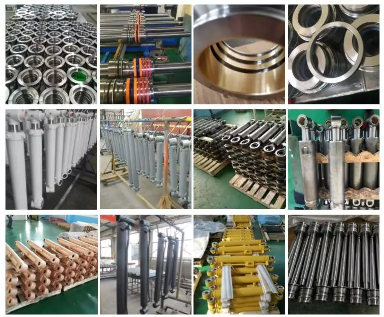
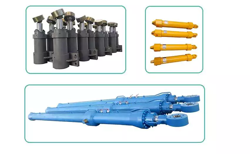
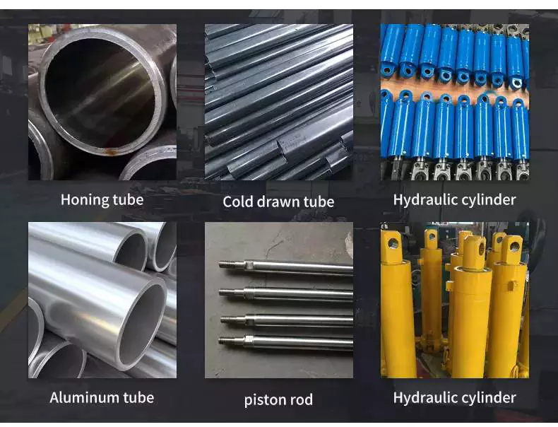
2.Product picture
| Type | Outside diameter (mm) |
Water capacity (L) |
Height (mm) |
Weight (kg) |
Service pressure (bar) |
Test pressure (bar) |
Design wall thickness (mm) |
Material |
| ISO9809 (TPED) |
219 | 20 | 715 | 28 | 150 | 250 | 5.7 | 37Mn |
| 25 | 865 | 33 | ||||||
| 32 | 1075 | 40 | ||||||
| 36 | 1195 | 44 | ||||||
| 37 | 1125 | 45 | ||||||
| 38 | 1255 | 46 | ||||||
| 40 | 1315 | 48 | ||||||
| 42 | 1375 | 50 | ||||||
| 45 | 1465 | 54 | ||||||
| 50 | 1615 | 60 |
Driveshaft structure and vibrations associated with it
The structure of the drive shaft is critical to its efficiency and reliability. Drive shafts typically contain claw couplings, rag joints and universal joints. Other drive shafts have prismatic or splined joints. Learn about the different types of drive shafts and how they work. If you want to know the vibrations associated with them, read on. But first, let’s define what a driveshaft is.
transmission shaft
As the demand on our vehicles continues to increase, so does the demand on our drive systems. Higher CO2 emission standards and stricter emission standards increase the stress on the drive system while improving comfort and shortening the turning radius. These and other negative effects can place significant stress and wear on components, which can lead to driveshaft failure and increase vehicle safety risks. Therefore, the drive shaft must be inspected and replaced regularly.
Depending on your model, you may only need to replace 1 driveshaft. However, the cost to replace both driveshafts ranges from $650 to $1850. Additionally, you may incur labor costs ranging from $140 to $250. The labor price will depend on your car model and its drivetrain type. In general, however, the cost of replacing a driveshaft ranges from $470 to $1850.
Regionally, the automotive driveshaft market can be divided into 4 major markets: North America, Europe, Asia Pacific, and Rest of the World. North America is expected to dominate the market, while Europe and Asia Pacific are expected to grow the fastest. Furthermore, the market is expected to grow at the highest rate in the future, driven by economic growth in the Asia Pacific region. Furthermore, most of the vehicles sold globally are produced in these regions.
The most important feature of the driveshaft is to transfer the power of the engine to useful work. Drive shafts are also known as propeller shafts and cardan shafts. In a vehicle, a propshaft transfers torque from the engine, transmission, and differential to the front or rear wheels, or both. Due to the complexity of driveshaft assemblies, they are critical to vehicle safety. In addition to transmitting torque from the engine, they must also compensate for deflection, angular changes and length changes.
type
Different types of drive shafts include helical shafts, gear shafts, worm shafts, planetary shafts and synchronous shafts. Radial protruding pins on the head provide a rotationally secure connection. At least 1 bearing has a groove extending along its circumferential length that allows the pin to pass through the bearing. There can also be 2 flanges on each end of the shaft. Depending on the application, the shaft can be installed in the most convenient location to function.
Propeller shafts are usually made of high-quality steel with high specific strength and modulus. However, they can also be made from advanced composite materials such as carbon fiber, Kevlar and fiberglass. Another type of propeller shaft is made of thermoplastic polyamide, which is stiff and has a high strength-to-weight ratio. Both drive shafts and screw shafts are used to drive cars, ships and motorcycles.
Sliding and tubular yokes are common components of drive shafts. By design, their angles must be equal or intersect to provide the correct angle of operation. Unless the working angles are equal, the shaft vibrates twice per revolution, causing torsional vibrations. The best way to avoid this is to make sure the 2 yokes are properly aligned. Crucially, these components have the same working angle to ensure smooth power flow.
The type of drive shaft varies according to the type of motor. Some are geared, while others are non-geared. In some cases, the drive shaft is fixed and the motor can rotate and steer. Alternatively, a flexible shaft can be used to control the speed and direction of the drive. In some applications where linear power transmission is not possible, flexible shafts are a useful option. For example, flexible shafts can be used in portable devices.
put up
The construction of the drive shaft has many advantages over bare metal. A shaft that is flexible in multiple directions is easier to maintain than a shaft that is rigid in other directions. The shaft body and coupling flange can be made of different materials, and the flange can be made of a different material than the main shaft body. For example, the coupling flange can be made of steel. The main shaft body is preferably flared on at least 1 end, and the at least 1 coupling flange includes a first generally frustoconical projection extending into the flared end of the main shaft body.
The normal stiffness of fiber-based shafts is achieved by the orientation of parallel fibers along the length of the shaft. However, the bending stiffness of this shaft is reduced due to the change in fiber orientation. Since the fibers continue to travel in the same direction from the first end to the second end, the reinforcement that increases the torsional stiffness of the shaft is not affected. In contrast, a fiber-based shaft is also flexible because it uses ribs that are approximately 90 degrees from the centerline of the shaft.
In addition to the helical ribs, the drive shaft 100 may also contain reinforcing elements. These reinforcing elements maintain the structural integrity of the shaft. These reinforcing elements are called helical ribs. They have ribs on both the outer and inner surfaces. This is to prevent shaft breakage. These elements can also be shaped to be flexible enough to accommodate some of the forces generated by the drive. Shafts can be designed using these methods and made into worm-like drive shafts.
vibration
The most common cause of drive shaft vibration is improper installation. There are 5 common types of driveshaft vibration, each related to installation parameters. To prevent this from happening, you should understand what causes these vibrations and how to fix them. The most common types of vibration are listed below. This article describes some common drive shaft vibration solutions. It may also be beneficial to consider the advice of a professional vibration technician for drive shaft vibration control.
If you’re not sure if the problem is the driveshaft or the engine, try turning on the stereo. Thicker carpet kits can also mask vibrations. Nonetheless, you should contact an expert as soon as possible. If vibration persists after vibration-related repairs, the driveshaft needs to be replaced. If the driveshaft is still under warranty, you can repair it yourself.
CV joints are the most common cause of third-order driveshaft vibration. If they are binding or fail, they need to be replaced. Alternatively, your CV joints may just be misaligned. If it is loose, you can check the CV connector. Another common cause of drive shaft vibration is improper assembly. Improper alignment of the yokes on both ends of the shaft can cause them to vibrate.
Incorrect trim height can also cause driveshaft vibration. Correct trim height is necessary to prevent drive shaft wobble. Whether your vehicle is new or old, you can perform some basic fixes to minimize problems. One of these solutions involves balancing the drive shaft. First, use the hose clamps to attach the weights to it. Next, attach an ounce of weight to it and spin it. By doing this, you minimize the frequency of vibration.
cost
The global driveshaft market is expected to exceed (xxx) million USD by 2028, growing at a compound annual growth rate (CAGR) of XX%. Its soaring growth can be attributed to several factors, including increasing urbanization and R&D investments by leading market players. The report also includes an in-depth analysis of key market trends and their impact on the industry. Additionally, the report provides a comprehensive regional analysis of the Driveshaft Market.
The cost of replacing the drive shaft depends on the type of repair required and the cause of the failure. Typical repair costs range from $300 to $750. Rear-wheel drive cars usually cost more. But front-wheel drive vehicles cost less than four-wheel drive vehicles. You may also choose to try repairing the driveshaft yourself. However, it is important to do your research and make sure you have the necessary tools and equipment to perform the job properly.
The report also covers the competitive landscape of the Drive Shafts market. It includes graphical representations, detailed statistics, management policies, and governance components. Additionally, it includes a detailed cost analysis. Additionally, the report presents views on the COVID-19 market and future trends. The report also provides valuable information to help you decide how to compete in your industry. When you buy a report like this, you are adding credibility to your work.
A quality driveshaft can improve your game by ensuring distance from the tee and improving responsiveness. The new material in the shaft construction is lighter, stronger and more responsive than ever before, so it is becoming a key part of the driver. And there are a variety of options to suit any budget. The main factor to consider when buying a shaft is its quality. However, it’s important to note that quality doesn’t come cheap and you should always choose an axle based on what your budget can handle.

