Product Description
GRH specialized in providing hydraulic components and solutions for hydraulic systems.
With continuous improvement and enthusiasm over the past 30 years, CHINAMFG has developed into an emerging power in the fluid power industry since it was established in 1986.
GRH (ZheJiang ) – International Sales Office
GRH (ZheJiang ) – Manufacturing Facility and Domestic Sales Office
Production description
About Us
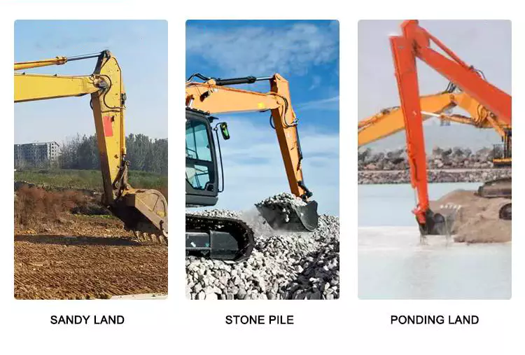
Application and Partners
Contact us!
| Certification: | GS, RoHS, CE, ISO9001 |
|---|---|
| Pressure: | Medium Pressure |
| Work Temperature: | Normal Temperature |
| Voltage: | 24V |
| Installation: | Horizontal |
| Material: | Aluminum Alloy |
| Customization: |
Available
|
|
|---|
What advancements in hydraulic cylinder technology have improved sealing and reliability?
Advancements in hydraulic cylinder technology have continuously contributed to improving sealing and reliability in hydraulic systems. These advancements aim to address common challenges such as leakage, wear, and failure of seals, ensuring optimal performance and longevity. Here are several key advancements that have significantly improved sealing and reliability in hydraulic cylinders:
1. High-Performance Sealing Materials:
– The development of advanced sealing materials has greatly improved the sealing capabilities of hydraulic cylinders. Traditional sealing materials like rubber have been replaced or enhanced with high-performance materials such as polyurethane, PTFE (polytetrafluoroethylene), and various composite materials. These materials offer superior resistance to wear, temperature, and chemical degradation, resulting in improved sealing performance and extended seal life.
2. Enhanced Seal Designs:
– Advancements in seal designs have focused on improving sealing efficiency and reliability. Innovative seal profiles, such as lip seals, wipers, and scrapers, have been developed to optimize fluid retention and prevent contamination. These designs provide better sealing performance, minimizing the risk of fluid leakage and maintaining system integrity. Additionally, improved seal geometries and manufacturing techniques ensure tighter tolerances, reducing the potential for seal failure due to misalignment or extrusion.
3. Integrated Seal and Bearing Systems:
– Hydraulic cylinders now incorporate integrated seal and bearing systems, where the sealing elements also serve as bearing surfaces. This design approach reduces the number of components and potential failure points, improving overall reliability. By integrating seals and bearings, the risk of seal damage or displacement due to excessive loads or misalignment is minimized, resulting in enhanced sealing performance and increased reliability.
4. Advanced Coatings and Surface Treatments:
– The application of advanced coatings and surface treatments to hydraulic cylinder components has significantly improved sealing and reliability. Coatings such as chrome plating or ceramic coatings enhance surface hardness, wear resistance, and corrosion resistance. These surface treatments provide a smoother and more durable surface for seals to operate against, reducing friction and improving sealing performance. Moreover, specialized coatings can also provide self-lubricating properties, reducing the need for additional lubrication and enhancing reliability.
5. Sealing System Monitoring and Diagnostic Technologies:
– The integration of monitoring and diagnostic technologies in hydraulic systems has revolutionized seal performance and reliability. Sensors and monitoring systems can detect and alert operators to potential seal failures or leaks before they escalate. Real-time monitoring of pressure, temperature, and seal performance parameters allows for proactive maintenance and early intervention, preventing costly downtime and ensuring optimal sealing and reliability.
6. Computational Modeling and Simulation:
– Computational modeling and simulation techniques have played a significant role in advancing hydraulic cylinder sealing and reliability. These tools enable engineers to analyze and optimize seal designs, fluid flow dynamics, and contact stresses. By simulating various operating conditions, potential issues such as seal extrusion, wear, or leakage can be identified and mitigated early in the design phase, resulting in improved sealing performance and enhanced reliability.
7. Systematic Maintenance Practices:
– Advances in hydraulic cylinder technology have also emphasized the importance of systematic maintenance practices to ensure sealing and overall system reliability. Regular inspection, lubrication, and replacement of seals, as well as routine system flushing and filtration, help prevent premature seal failure and optimize sealing performance. Implementing preventive maintenance schedules and adhering to recommended service intervals contribute to extended seal life and enhanced reliability.
In summary, advancements in hydraulic cylinder technology have led to significant improvements in sealing and reliability. High-performance sealing materials, enhanced seal designs, integrated seal and bearing systems, advanced coatings and surface treatments, sealing system monitoring and diagnostics, computational modeling and simulation, and systematic maintenance practices have all played key roles in achieving optimal sealing performance and increased reliability. These advancements have resulted in more efficient and dependable hydraulic systems, minimizing leakage, wear, and failure of seals, and ultimately improving the overall performance and longevity of hydraulic cylinders in diverse applications.

Customization of Hydraulic Cylinders for Marine and Offshore Applications
Yes, hydraulic cylinders can be customized for use in marine and offshore applications. These environments present unique challenges, such as exposure to corrosive saltwater, high humidity, and extreme operating conditions. Customization allows hydraulic cylinders to meet the specific requirements and withstand the harsh conditions encountered in marine and offshore settings. Let’s delve into the details of how hydraulic cylinders can be customized for marine and offshore applications:
- Corrosion Resistance: Marine and offshore environments expose hydraulic cylinders to corrosive elements, such as saltwater. To mitigate corrosion, hydraulic cylinders can be customized with materials and surface treatments that provide enhanced corrosion resistance. For example, cylinders can be constructed from stainless steel or coated with protective layers like chrome plating or specialized coatings to withstand the corrosive effects of saltwater.
- Sealing and Environmental Protection: Hydraulic cylinders for marine and offshore applications require robust sealing systems to prevent water ingress and protect internal components. Customized sealing solutions, such as high-quality seals, wipers, and gaskets, can be employed to ensure effective sealing and resistance to water, debris, and contaminants. Additionally, hydraulic cylinders can be designed with protective features like bellows or boots to shield vulnerable areas from environmental elements.
- High-Pressure and Shock Resistance: Marine and offshore operations may involve high-pressure hydraulic systems and encounters with dynamic loads or shocks. Customized hydraulic cylinders can be engineered to withstand these demanding conditions. They can be designed with reinforced construction, thicker walls, and specialized components to handle high-pressure applications and absorb shock loads, ensuring reliable performance and durability.
- Temperature and Fluid Compatibility: Marine and offshore applications can expose hydraulic cylinders to extreme temperature variations and specific fluid requirements. Customization allows the selection of materials, seals, and fluids compatible with the anticipated temperature range and the specific fluid being used. Hydraulic cylinders can be tailored to maintain optimal performance and reliability under challenging temperature conditions and with the designated fluid type.
- Mounting and Integration: Customized hydraulic cylinders can be designed to facilitate easy integration and mounting within marine and offshore machinery. Mounting options can be tailored to suit the available space and structural requirements of the equipment. Additionally, customized hydraulic cylinder designs can incorporate features for easy maintenance, accessibility, and connection to the hydraulic system, ensuring convenient installation and serviceability in marine and offshore applications.
In summary, hydraulic cylinders can be customized to meet the unique demands of marine and offshore applications. Customization enables the integration of corrosion-resistant materials, robust sealing systems, high-pressure and shock-resistant designs, temperature and fluid compatibility, as well as optimized mounting and integration features. By tailoring hydraulic cylinders to the specific requirements of marine and offshore environments, reliable performance, extended service life, and efficient operation can be achieved in these challenging operating conditions.
How do hydraulic cylinders generate force and motion using hydraulic fluid?
Hydraulic cylinders generate force and motion by utilizing the principles of fluid mechanics, specifically Pascal’s law, in conjunction with the properties of hydraulic fluid. The process involves the conversion of hydraulic energy into mechanical force and linear motion. Here’s a detailed explanation of how hydraulic cylinders achieve this:
1. Pascal’s Law:
– Hydraulic cylinders operate based on Pascal’s law, which states that when pressure is applied to a fluid in a confined space, it is transmitted equally in all directions. In the context of hydraulic cylinders, this means that when hydraulic fluid is pressurized, the force is evenly distributed throughout the fluid and transmitted to all surfaces in contact with the fluid.
2. Hydraulic Fluid and Pressure:
– Hydraulic systems use a specialized fluid, typically hydraulic oil, as the working medium. This fluid is stored in a reservoir and circulated through the system by a hydraulic pump. The pump pressurizes the fluid, creating hydraulic pressure that can be controlled and directed to various components, including hydraulic cylinders.
3. Cylinder Design and Components:
– Hydraulic cylinders consist of several key components, including a cylindrical barrel, a piston, a piston rod, and various seals. The barrel is a hollow tube that houses the piston and allows for fluid flow. The piston divides the cylinder into two chambers: the rod side and the cap side. The piston rod extends from the piston and provides a connection point for external loads. Seals are used to prevent fluid leakage and maintain hydraulic pressure within the cylinder.
4. Fluid Input and Motion:
– To generate force and motion, hydraulic fluid is directed into one side of the cylinder, creating pressure on the corresponding surface of the piston. This pressure is transmitted through the fluid to the other side of the piston.
5. Force Generation:
– The force generated by a hydraulic cylinder is a result of the pressure applied to a specific surface area of the piston. The force exerted by the hydraulic cylinder can be calculated using the formula: Force = Pressure × Area. The area is determined by the diameter of the piston or the piston rod, depending on which side of the cylinder the fluid is acting upon.
6. Linear Motion:
– As the pressurized hydraulic fluid acts on the piston, it generates a force that moves the piston in a linear direction within the cylinder. This linear motion is transferred to the piston rod, which extends or retracts accordingly. The piston rod can be connected to external components or machinery, allowing the generated force to perform various tasks, such as lifting, pushing, pulling, or controlling mechanisms.
7. Control and Regulation:
– The force and motion generated by hydraulic cylinders can be controlled and regulated by adjusting the flow of hydraulic fluid into the cylinder. By regulating the flow rate, pressure, and direction of the fluid, the speed, force, and direction of the cylinder’s movement can be precisely controlled. This control allows for accurate positioning, smooth operation, and synchronization of multiple cylinders in complex machinery.
8. Return and Recirculation of Fluid:
– After the hydraulic cylinder completes its stroke, the hydraulic fluid on the opposite side of the piston needs to be returned to the reservoir. This is typically achieved through hydraulic valves that control the flow direction, allowing the fluid to return and be recirculated in the system for further use.
In summary, hydraulic cylinders generate force and motion by utilizing the principles of Pascal’s law. Pressurized hydraulic fluid acts on the piston, creating force that moves the piston in a linear direction. This linear motion is transferred to the piston rod, allowing the generated force to perform various tasks. By controlling the flow of hydraulic fluid, the force and motion of hydraulic cylinders can be precisely regulated, contributing to their versatility and wide range of applications in machinery.


editor by CX 2023-10-28
China Customize 220V-380V Hydraulic System Hydraulic Power Unit,Station Electric Hydraulic Power Pack agricultural hydraulic cylinders
Condition: New
Warranty: 1.5 years
Showroom Place: None
Sort: Hydraulic Electrical power Units
Strain: 16Mpa-70Mpa(2250 CZPT – 10150 PSI)
Construction: Piston Cylinder
Fat: 36
Electricity: Buyer Prerequisite
Dimension(L*W*H): Customer Need
Product name: Hydraulic Program Electricity Unit Station Electric powered Hydraulic electricity pack
Certification: ISO9 43410-12490 for CZPT COROLLA and sound. secure to use. Can be switched from DC 12V to 24V or AC 220Vto 38ov, and the customized input voltage is accessible. Pump:Excellent metallic substance and high-precision producing, Lengthy existence,substantial mechanical efficiency and trustworthiness. Valve group:Basic in Procedure and management, Large stage of automation,Easy to modify route, Straightforward to change the system rotate motion to the straight line reciprocating motion with no altering the motor route of rotation Cooling admirer:High heat transfer efficiency, Preserve the hydraulic Oil at the correct temperature. Q1: Are You Manufacture or Trade Firm? A1: We are manufacture, NK sequence NK1617 Bearings NK RNA NKS Needle roller bearings with out inner ring we have 10 several years knowledge for provide Metal content and goods in domestic.Q2: How can we ensure quality? A2: Always a pre-creation sample prior to mass productionAlways ultimate Inspection just before cargoQ3: What is your terms of payment ?A3: 1.T/T: 30% deposit in progress, the equilibrium 70% compensated just before shipment2.thirty% down payment, the stability 70% compensated in opposition to L/C at sight3.CZPT negotiationQ4: Can you give Certificates for aluminum supplies ? A4:Yes,we can supply MTC-Material Examination Certification. Q5: Can you offer sample? A5: Of course, we can offer you sample, but you require to pay for the sample and freight to begin with. We will return the sample fee afteryou make an buy.

The Basics of Hydraulic Cylinders
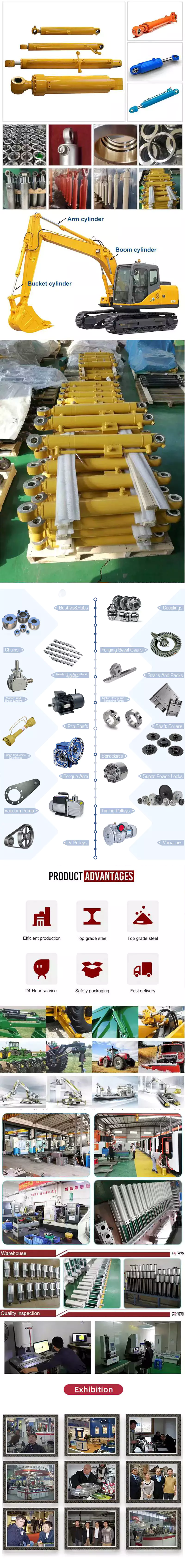
Basically a hydraulic cylinder is a mechanical actuator which can be used for giving unidirectional force. It has various applications in civil engineering, construction equipment, manufacturing machinery and elevators.
Single acting vs double acting
Generally speaking, single acting and double acting hydraulic cylinders function differently. Double acting cylinders have two ports, and apply pressure on both sides of the piston. Single acting cylinders have a single port.
Hydraulic cylinders are used in a wide variety of applications, including manufacturing machinery, construction equipment, and civil engineering. Their main use is on mobile equipment such as graders and excavators. They are also used in reciprocating engines and hydraulic rams.
Single acting hydraulic cylinders are generally smaller and more compact than double acting cylinders. They are also simpler in design and require less maintenance. They are suitable for heavy-duty applications such as lifting and ejecting parts from conveyor belts. They are also cheaper to manufacture. However, they have a limited range of motion, and have limited power and control.
Double acting cylinders, on the other hand, offer more flexibility, faster operation, and greater power. They are also better suited for applications that require precise retraction control. They are more durable than single acting cylinders, and are commonly used in heavy industrial applications. They also have more design variation.
In order to determine whether you need a single acting or double acting cylinder, you should first consider your power requirements. Single acting cylinders are better suited for applications that require only a small amount of force, but require several stroke cycles. Double acting cylinders are suited for applications that require more force, but require a higher number of stroke cycles.
Single acting cylinders are more economical to buy and install, but they are not as compact as double acting cylinders. They are also not as reliable as double acting cylinders. In addition, they may require a second port to convert a single acting cylinder into a double acting cylinder.
Piston rod
During the design phase of a hydraulic cylinder, many factors must be considered. These include the function, materials, and the environment in which the cylinder will be used.
The most important part of the hydraulic cylinder is the rod. It performs the reciprocating motion and is attached to the piston by threads. It also acts as the structural component of the cylinder.
The rod itself is made from chrome plated steel and is usually 10 to 30 millimeters thick. It is plated with a thick layer of chromium to increase wear resistance and temperature resistance. The rod also has an o-ring on its end to prevent the high-pressure oil from escaping.
The rod is connected to the piston by a backup ring and two o-rings. The o-rings keep the rod centered in the barrel, while the backup rings protect the o-rings from escaping when high pressures are applied from the opposite side.
The most important feature of the piston rod is its buckling resistance. The rod may be solid, hollow, or heat-treated. The buckling resistance of a rod depends on its length and its diameter. The longer the rod, the less force it needs to withstand a buckling load.
Another important feature of the rod is its slenderness ratio. This ratio is calculated by measuring the effective length of the rod. This ratio is usually calculated by using Euler’s theory.
The cylinder head is another important part of the hydraulic cylinder. The head has ports that allow hydraulic fluid to enter and exit the barrel. It also has a check valve to prevent oil from leaking out.
The cylinder head also serves as a mechanical stop for the piston. It has two seals: a gland seal and an internal seal. The gland seal prevents the high-pressure oil from escaping, while the internal seal ensures that the o-ring seal is in place.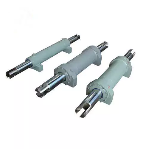
Welded body vs flanged connection
Generally, there are two kinds of connections for hydraulic cylinders: flanged and welded body. The flange connection is usually used in applications where there is exceptionally high pressure. A welded body connection can be used in places where space is limited. It also improves the overall appearance of the equipment.
Hydraulic cylinders are used in a variety of applications, including earth moving equipment, metal sheet shearing machines, and hydraulic bending machines. They are also used in particle board making hot press machines. The majority of hydraulic cylinders are made from alloy steel combinations.
These materials are prone to rusting, especially when used in humid environments. They may also require coating to prevent corrosion. Hydraulic cylinders can be made of stainless steel or alloy steel. Stainless steel is usually used in marine environments because of its corrosion resistance.
Hydraulic cylinders come in a variety of designs, including single acting cylinders, double acting cylinders, and telescopic cylinders. Single acting cylinders are designed for pushing motion, while double acting cylinders are designed for a linear motion. They are available with threaded, socket weld, or welded body connections.
The rod of a hydraulic cylinder operates outside of the barrel, pushing hydraulic fluid inside the barrel. The piston rod needs to be protected from wear, and the outer diameter of the piston rod is usually coated with a corrosion-resistant surface.
Hydraulic cylinders are typically made of carbon steel, stainless steel, or alloy steel. There are a variety of coatings available, including chrome (nickel) plating, laser cladding, and hard chrome plating.
The most important seal in hydraulic cylinders is the rod seal. This seal needs to be slow to wear, and it needs to be able to resist multiple rod movements. It must also be able to remove contaminants from the hydraulic fluid.
Pneumatic actuators vs hydraulic actuators
Compared to hydraulic actuators, pneumatic actuators are cheaper and less powerful. However, they offer higher uptime and increased productivity. This makes them a good choice for light to medium duty applications.
Pneumatic actuators use air pressure instead of hydraulic fluid, and they provide a reliable motion that is ideal for window manufacturing. They have a simple design that reduces maintenance. They can be used in various applications, including food production, automotive manufacturing, and industrial machinery.
Hydraulic actuators are better suited for heavy duty applications. They can handle higher pressures and generate more force than pneumatic actuators. But they can leak fluid, which can invite contamination. They can also be noisy, without the use of noise-reducing equipment.
Hydraulics also require pumps and reservoirs for fluid. There are also valves, pistons, and companion parts to maintain the system. It is important to check for leaks and maintain the system.
Hydraulic actuators are used in heavy construction equipment, nail guns, precision drills, and moving machinery. Hydraulic cylinders provide 25 times the force of pneumatic cylinders.
Hydraulic systems can be a good choice for heavy duty applications, but they can also cause more problems. For example, the pressures can be very high, and they can leak fluid. Hydraulics require regular maintenance, which increases the overall cost of ownership. They can also lead to contamination of the internal working parts of the system.
The biggest advantage of hydraulic actuators is their ability to create and hold torque. It’s important to monitor the temperature of the fluid to avoid leaks. If there is a leak, the fluid can be contaminated and damage internal working parts.
Hydraulic actuators require more care and maintenance, and they may be more expensive than pneumatic actuators. The cost of maintenance may also affect the lifespan of the device.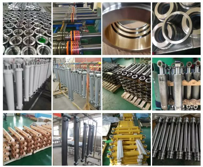
Cushioned vs non-cushioned cylinders
Depending on the application, cushioned hydraulic cylinders can be used as a cost-effective and useful tool for reducing shock loads. The cushioning can take a variety of forms, from external shock absorbers to internal cushions.
Cushioning is the process of decelerating the cylinder rod near the end of its stroke. This reduces vibration and reduces stresses on components. However, too much cushioning can reduce the efficiency of the machine, especially for pneumatic cylinders.
The cushioning effect is achieved by restricting the flow of hydraulic fluid exiting the cylinder port. This is achieved through a small orifice that allows the flow to be controlled. The smaller the orifice, the more controllable the cushioning effect.
A typical example is a double-acting cylinder with double-sided cushioning. The cylinder is constructed with a check valve oriented from port A to port B. This valve is set to operate from a minimum of 10 millimeters before the end of the stroke.
The cushioning effect can be regulated externally with an adjustable screw. In order to determine the amount of cushioning required, it is important to consider factors such as cylinder size, stroke, and application.
In addition to being able to control the flow of hydraulic fluid, the cushioning effect can also be used to protect the entire system. It can be used to restrict the exiting flow of hydraulic fluid so that the incoming flow can reach maximum pressure.
Cushioning can be used in conjunction with other methods to reduce shock loads. For example, a fast start-up method can reduce the impact force of the cylinder. A cushion design can also increase the rate at which fluid returns to the cylinder when it leaves the cushion.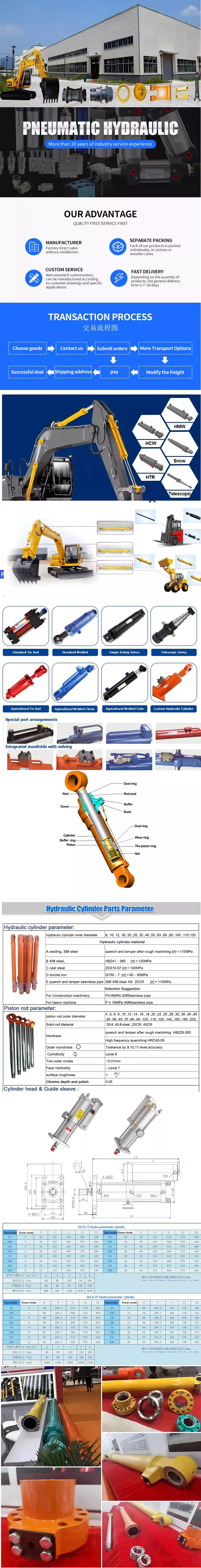
editor by czh 2023-06-27
China high quality Diesel Power Pack Hydraulic Splitter Cylinder for Concrete near me manufacturer
Product Description
Enormous splitting force up to 413 tons
Dust free and near silent operation
Vibration free
Light weigh
PRODRLL SPLITTING CYLINDERS:Handheld Demolition devices, which controllably split material with the use of hydraulic pressure: 400 TONS OF SPLITTING FORCE IN ONE-HAND.Above all they convince when larger conventional demolition devices are ruled-out because they produce dust, flying debris, vibration, noise and possibly exhaust fumes. Important Fields of application: Demolition of concrete and reinforced concrete.
Prodrill hydraulic splitter, also known as rock splitter and darda splitter, is a type of portable hydraulic tool that is used in demolition jobs which involve breaking large blocks of concrete and rocks. Its use in geology was first popularized by volcanologist CZPT Richardson.
There is also a larger excavator mounted rock splitter from Pro Drill Rock Splitter which is suitable for excavation of large volumes of hard rock where blasting is not practical or allowed
Hydraulic rock splitters consist of 2 wedges which are inserted in a pre-drilled hole and a hydraulic cylinder is pushing out a center wedge between the 2 side wedges forcing them to separate.
Splitting cylinder
| Diameter Borehole | 35-38 mm |
| Min. Depth Borehole | 540 mm |
| Diameter Borehole | 45-48 mm |
| Min. Depth Borehole | 410 mm |
Worm Gear Motors
Worm gear motors are often preferred for quieter operation because of the smooth sliding motion of the worm shaft. Unlike gear motors with teeth, which may click as the worm turns, worm gear motors can be installed in a quiet area. In this article, we will talk about the CZPT whirling process and the various types of worms available. We’ll also discuss the benefits of worm gear motors and worm wheel.
worm gear
In the case of a worm gear, the axial pitch of the ring pinion of the corresponding revolving worm is equal to the circular pitch of the mating revolving pinion of the worm gear. A worm with 1 start is known as a worm with a lead. This leads to a smaller worm wheel. Worms can work in tight spaces because of their small profile.
Generally, a worm gear has high efficiency, but there are a few disadvantages. Worm gears are not recommended for high-heat applications because of their high level of rubbing. A full-fluid lubricant film and the low wear level of the gear reduce friction and wear. Worm gears also have a lower wear rate than a standard gear. The worm shaft and worm gear is also more efficient than a standard gear.
The worm gear shaft is cradled within a self-aligning bearing block that is attached to the gearbox casing. The eccentric housing has radial bearings on both ends, enabling it to engage with the worm gear wheel. The drive is transferred to the worm gear shaft through bevel gears 13A, 1 fixed at the ends of the worm gear shaft and the other in the center of the cross-shaft.
worm wheel
In a worm gearbox, the pinion or worm gear is centered between a geared cylinder and a worm shaft. The worm gear shaft is supported at either end by a radial thrust bearing. A gearbox’s cross-shaft is fixed to a suitable drive means and pivotally attached to the worm wheel. The input drive is transferred to the worm gear shaft 10 through bevel gears 13A, 1 of which is fixed to the end of the worm gear shaft and the other at the centre of the cross-shaft.
Worms and worm wheels are available in several materials. The worm wheel is made of bronze alloy, aluminum, or steel. Aluminum bronze worm wheels are a good choice for high-speed applications. Cast iron worm wheels are cheap and suitable for light loads. MC nylon worm wheels are highly wear-resistant and machinable. Aluminum bronze worm wheels are available and are good for applications with severe wear conditions.
When designing a worm wheel, it is vital to determine the correct lubricant for the worm shaft and a corresponding worm wheel. A suitable lubricant should have a kinematic viscosity of 300 mm2/s and be used for worm wheel sleeve bearings. The worm wheel and worm shaft should be properly lubricated to ensure their longevity.
Multi-start worms
A multi-start worm gear screw jack combines the benefits of multiple starts with linear output speeds. The multi-start worm shaft reduces the effects of single start worms and large ratio gears. Both types of worm gears have a reversible worm that can be reversed or stopped by hand, depending on the application. The worm gear’s self-locking ability depends on the lead angle, pressure angle, and friction coefficient.
A single-start worm has a single thread running the length of its shaft. The worm advances 1 tooth per revolution. A multi-start worm has multiple threads in each of its threads. The gear reduction on a multi-start worm is equal to the number of teeth on the gear minus the number of starts on the worm shaft. In general, a multi-start worm has 2 or 3 threads.
Worm gears can be quieter than other types of gears because the worm shaft glides rather than clicking. This makes them an excellent choice for applications where noise is a concern. Worm gears can be made of softer material, making them more noise-tolerant. In addition, they can withstand shock loads. Compared to gears with toothed teeth, worm gears have a lower noise and vibration rate.
CZPT whirling process
The CZPT whirling process for worm shafts raises the bar for precision gear machining in small to medium production volumes. The CZPT whirling process reduces thread rolling, increases worm quality, and offers reduced cycle times. The CZPT LWN-90 whirling machine features a steel bed, programmable force tailstock, and five-axis interpolation for increased accuracy and quality.
Its 4,000-rpm, 5-kW whirling spindle produces worms and various types of screws. Its outer diameters are up to 2.5 inches, while its length is up to 20 inches. Its dry-cutting process uses a vortex tube to deliver chilled compressed air to the cutting point. Oil is also added to the mixture. The worm shafts produced are free of undercuts, reducing the amount of machining required.
Induction hardening is a process that takes advantage of the whirling process. The induction hardening process utilizes alternating current (AC) to cause eddy currents in metallic objects. The higher the frequency, the higher the surface temperature. The electrical frequency is monitored through sensors to prevent overheating. Induction heating is programmable so that only certain parts of the worm shaft will harden.
Common tangent at an arbitrary point on both surfaces of the worm wheel
A worm gear consists of 2 helical segments with a helix angle equal to 90 degrees. This shape allows the worm to rotate with more than 1 tooth per rotation. A worm’s helix angle is usually close to 90 degrees and the body length is fairly long in the axial direction. A worm gear with a lead angle g has similar properties as a screw gear with a helix angle of 90 degrees.
The axial cross section of a worm gear is not conventionally trapezoidal. Instead, the linear part of the oblique side is replaced by cycloid curves. These curves have a common tangent near the pitch line. The worm wheel is then formed by gear cutting, resulting in a gear with 2 meshing surfaces. This worm gear can rotate at high speeds and still operate quietly.
A worm wheel with a cycloid pitch is a more efficient worm gear. It reduces friction between the worm and the gear, resulting in greater durability, improved operating efficiency, and reduced noise. This pitch line also helps the worm wheel engage more evenly and smoothly. Moreover, it prevents interference with their appearance. It also makes worm wheel and gear engagement smoother.
Calculation of worm shaft deflection
There are several methods for calculating worm shaft deflection, and each method has its own set of disadvantages. These commonly used methods provide good approximations but are inadequate for determining the actual worm shaft deflection. For example, these methods do not account for the geometric modifications to the worm, such as its helical winding of teeth. Furthermore, they overestimate the stiffening effect of the gearing. Hence, efficient thin worm shaft designs require other approaches.
Fortunately, several methods exist to determine the maximum worm shaft deflection. These methods use the finite element method, and include boundary conditions and parameter calculations. Here, we look at a couple of methods. The first method, DIN 3996, calculates the maximum worm shaft deflection based on the test results, while the second one, AGMA 6022, uses the root diameter of the worm as the equivalent bending diameter.
The second method focuses on the basic parameters of worm gearing. We’ll take a closer look at each. We’ll examine worm gearing teeth and the geometric factors that influence them. Commonly, the range of worm gearing teeth is 1 to four, but it can be as large as twelve. Choosing the teeth should depend on optimization requirements, including efficiency and weight. For example, if a worm gearing needs to be smaller than the previous model, then a small number of teeth will suffice.

