Product Description
Welcome to CHINAMFG HYDRAULICS.
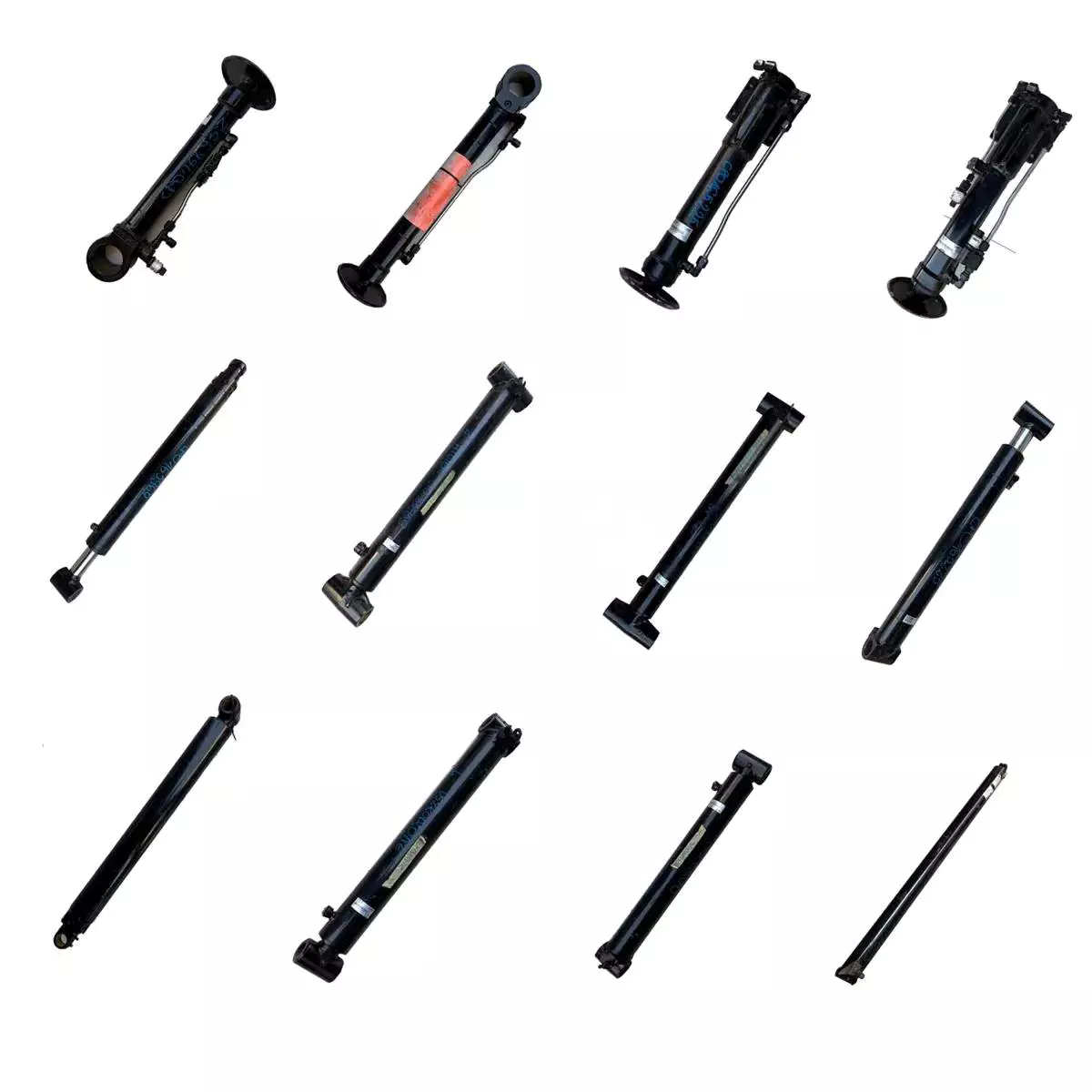
FLUTEC HYDRAULICS is an expert at designing and manufacturing a broad range of custom engineered hydraulic cylinders and cylinder systems as well as custom engineered press bolster plates. We are proud to offer superior quality products and services for various applications including industrial, construction, mobile, agricultural, mining, steel mill, hydraulic press, etc. Our highly skilled team and modern technical facilities allow us to manufacture large bore hydraulic cylinders and long stroke hydraulic cylinders with 100% confidence and assurance.
We understand our customers need dependable quality and excellent services with affordable cost to stay ahead in today’s highly competitive market. CHINAMFG HYDRAULICS can meet those requirements with our robust, efficient and long life products together with prompt services.
To be mentioned, our sales team is strictly trained both in technology and language. They are full of experiences in fluid power and machinery. We are glad to personally visit our customers to work better.
Technical Data
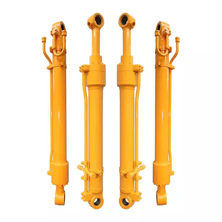
| Cylinder Type | Mill type, Head Bolted, Base Welded |
| Bore Diameter | Up to 2500mm |
| Rod Diameter | Up to 2000mm |
| Stroke Length | Up to 20,000mm |
| Piston Rod Material | AISI 1045, AISI 4140, AISI 4340, 20MnV6 |
| Rod Surface Treatment | Hard chrome plated, Chrome/Nickel plated, Ceramic coated |
| Tube Material | Carbon steel AISI1045 or ST52.3, Alloy steel AISI4140, Stainless steel 2Cr13 or 1Cr17Ni2 |
| Tube Surface Painting | Colors according to RAL and thickness according to customer needs |
| Mounting Type | Clevis, Cross tube, Flange, Trunnion, Tang, Thread |
| Design Pressure | Up to 40Mpa |
| Seal Kits Type | PARKER, MERKEL, HALLITE, NOK, TRELLEBORG |
| Quality Assurance | 1 year |
| Certificate | SGS, BV, ABS ,GL, DNV etc. |
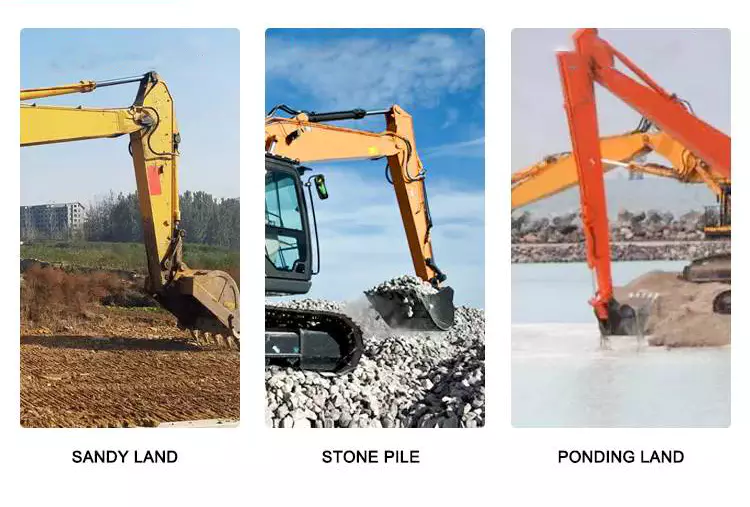
| Application | Heavy industry, steel mill, Hydraulic press, etc. |
Quality Assurance
| Quality Process | Our quality management system is certified to ISO 9001 |
| Quality control standards include material records, process control plans, Manufacturing approvals and inspection data |
|
| Testing Standards | All products undergo 100% pressure testing 1.5 times the maximum allowable working pressure or to customer specifications |
| Static and dynamic pressure testing. | |
| Ultraviolet leak detection technology. | |
| Non-destructive testing. | |
| Fluid Cleanliness | Real-time monitoring and test phase documentation |
| Independent sampling and oil diagnostic control |
| Certification: | ISO9001, Dnv, SGS, BV, ABS, Gl |
|---|---|
| Pressure: | Medium Pressure |
| Work Temperature: | Normal Temperature |
| Acting Way: | Double Acting |
| Working Method: | Straight Trip |
| Adjusted Form: | Regulated Type |
| Customization: |
Available
|
|
|---|
Can hydraulic cylinders be retrofitted onto existing equipment for improved functionality?
Yes, hydraulic cylinders can be retrofitted onto existing equipment to enhance functionality and performance. Retrofitting hydraulic cylinders onto existing machinery or equipment offers several benefits, including increased power, improved control, enhanced precision, and versatility. Here’s a detailed explanation of how hydraulic cylinders can be retrofitted onto existing equipment for improved functionality:
1. Increased Power:
– Retrofitting hydraulic cylinders allows for the addition of hydraulic power to the existing equipment. By integrating hydraulic cylinders, the equipment can generate higher forces and handle heavier loads. This increased power enables the equipment to perform tasks that were previously challenging or impossible. For example, a retrofit hydraulic cylinder on a crane can enhance its lifting capacity and enable it to handle heavier loads more efficiently.
2. Improved Control:
– Hydraulic cylinders provide precise control over the motion and positioning of equipment. By retrofitting hydraulic cylinders, operators gain better control over the speed, force, and direction of movement. The addition of hydraulic control valves and a hydraulic power unit allows for fine-tuning of the equipment’s operation. Improved control facilitates safer and more efficient operation, reducing the risk of damage and improving overall productivity.
3. Enhanced Precision:
– Retrofitting hydraulic cylinders onto existing equipment can significantly improve precision and accuracy. Hydraulic systems offer precise control over movement, enabling smooth and controlled motion. This enhanced precision is beneficial in applications where precise positioning or repetitive movements are required. For instance, retrofitting hydraulic cylinders onto a robotic arm can enhance its accuracy and repeatability, making it more suitable for tasks that demand high precision.
4. Versatility and Adaptability:
– Retrofitting hydraulic cylinders can increase the versatility and adaptability of existing equipment. Hydraulic systems can be easily integrated with various types of machinery, allowing for the utilization of hydraulic power across different applications. The modular nature of hydraulic components facilitates the retrofitting process, enabling the equipment to perform a broader range of tasks. This versatility is particularly advantageous in industries where equipment needs to adapt to changing operational requirements.
5. Retrofit Kits and Customization:
– Manufacturers often provide retrofit kits that include all the necessary components for integrating hydraulic cylinders onto existing equipment. These kits typically consist of hydraulic cylinders, mounting brackets, hoses, fittings, control valves, and other required accessories. Retrofit kits simplify the retrofitting process and ensure compatibility between the hydraulic components and the existing equipment. Additionally, manufacturers can offer customization options to tailor the retrofit solution to specific equipment and application needs.
6. Cost-Effective Solution:
– Retrofitting hydraulic cylinders onto existing equipment can be a cost-effective solution compared to purchasing new machinery. By leveraging the existing equipment’s structural framework and mechanical components, the overall cost of upgrading can be reduced. Retrofitting also minimizes downtime since the equipment does not need to be completely replaced. Furthermore, the improved functionality and performance resulting from the retrofit can lead to increased productivity and cost savings in the long run.
7. Professional Installation and Expertise:
– Retrofitting hydraulic cylinders onto existing equipment often requires professional installation and expertise. Working with experienced hydraulic system integrators or manufacturers ensures proper installation, compatibility, and optimal performance of the retrofit solution. These professionals can assess the existing equipment, recommend suitable hydraulic components, and carry out the retrofitting process efficiently. Their knowledge and expertise contribute to the successful integration of hydraulic cylinders and the overall improvement of equipment functionality.
In summary, hydraulic cylinders can indeed be retrofitted onto existing equipment to improve functionality. This retrofitting process offers advantages such as increased power, improved control, enhanced precision, versatility, cost-effectiveness, and access to retrofit kits and customization options. By retrofitting hydraulic cylinders, existing equipment can be upgraded to meet evolving operational needs, extend its lifespan, and enhance overall performance.
Ensuring Controlled and Safe Force Application in Heavy Machinery with Hydraulic Cylinders
Hydraulic cylinders play a critical role in heavy machinery by ensuring controlled and safe force application. The ability to exert and control high forces is essential for heavy machinery operations, such as lifting, pressing, pushing, or pulling heavy loads. Let’s explore how hydraulic cylinders ensure controlled and safe force application in heavy machinery:
- Force Control: Hydraulic cylinders provide precise force control capabilities. The hydraulic system’s pressure can be adjusted to regulate the force exerted by the cylinder. This control allows operators to apply the necessary force for a specific task while ensuring it remains within safe limits. By accurately controlling the force, hydraulic cylinders help prevent excessive force that could damage the machinery or compromise the safety of the operation.
- Load Balancing: In heavy machinery, multiple hydraulic cylinders are often used in conjunction to distribute and balance the applied force. By using multiple cylinders, the load can be evenly distributed across the machinery, minimizing stress concentrations and ensuring controlled force application. This load balancing approach enhances the stability and safety of the machinery, preventing uneven loading that could lead to structural issues or instability.
- Safety Valves: Hydraulic systems in heavy machinery are equipped with safety valves to protect against excessive force or overloading. Safety valves are designed to release hydraulic fluid from the cylinder when the force exceeds a predetermined threshold. This prevents the force from reaching dangerous levels, safeguarding the machinery and preventing potential accidents or damage. Safety valves provide an additional layer of safety and ensure controlled force application even in unexpected circumstances.
- Pressure Relief Systems: Hydraulic cylinders incorporate pressure relief systems to further enhance safety. These systems are designed to relieve excess pressure in the hydraulic system, which could occur due to factors such as thermal expansion or system malfunctions. By relieving excess pressure, the pressure relief systems prevent sudden and uncontrolled force surges, maintaining safe and controlled force application in heavy machinery.
- Structural Integrity: Hydraulic cylinders are designed to withstand the high forces and loads associated with heavy machinery applications. The cylinders are constructed using robust materials, such as high-strength steel, and undergo rigorous testing to ensure their structural integrity. This ensures that the cylinders can safely handle the forces applied during heavy machinery operations without experiencing failures or deformations that could compromise the safety and controlled force application.
In summary, hydraulic cylinders ensure controlled and safe force application in heavy machinery through force control, load balancing, safety valves, pressure relief systems, and robust structural design. These features and design considerations enable operators to exert the necessary force while maintaining safety and preventing excessive loads or force surges. By incorporating hydraulic cylinders into heavy machinery, manufacturers can achieve controlled force application, enhance operational safety, and protect the machinery from damage or failure.
How do hydraulic cylinders generate force and motion using hydraulic fluid?
Hydraulic cylinders generate force and motion by utilizing the principles of fluid mechanics, specifically Pascal’s law, in conjunction with the properties of hydraulic fluid. The process involves the conversion of hydraulic energy into mechanical force and linear motion. Here’s a detailed explanation of how hydraulic cylinders achieve this:
1. Pascal’s Law:
– Hydraulic cylinders operate based on Pascal’s law, which states that when pressure is applied to a fluid in a confined space, it is transmitted equally in all directions. In the context of hydraulic cylinders, this means that when hydraulic fluid is pressurized, the force is evenly distributed throughout the fluid and transmitted to all surfaces in contact with the fluid.
2. Hydraulic Fluid and Pressure:
– Hydraulic systems use a specialized fluid, typically hydraulic oil, as the working medium. This fluid is stored in a reservoir and circulated through the system by a hydraulic pump. The pump pressurizes the fluid, creating hydraulic pressure that can be controlled and directed to various components, including hydraulic cylinders.
3. Cylinder Design and Components:
– Hydraulic cylinders consist of several key components, including a cylindrical barrel, a piston, a piston rod, and various seals. The barrel is a hollow tube that houses the piston and allows for fluid flow. The piston divides the cylinder into two chambers: the rod side and the cap side. The piston rod extends from the piston and provides a connection point for external loads. Seals are used to prevent fluid leakage and maintain hydraulic pressure within the cylinder.
4. Fluid Input and Motion:
– To generate force and motion, hydraulic fluid is directed into one side of the cylinder, creating pressure on the corresponding surface of the piston. This pressure is transmitted through the fluid to the other side of the piston.
5. Force Generation:
– The force generated by a hydraulic cylinder is a result of the pressure applied to a specific surface area of the piston. The force exerted by the hydraulic cylinder can be calculated using the formula: Force = Pressure × Area. The area is determined by the diameter of the piston or the piston rod, depending on which side of the cylinder the fluid is acting upon.
6. Linear Motion:
– As the pressurized hydraulic fluid acts on the piston, it generates a force that moves the piston in a linear direction within the cylinder. This linear motion is transferred to the piston rod, which extends or retracts accordingly. The piston rod can be connected to external components or machinery, allowing the generated force to perform various tasks, such as lifting, pushing, pulling, or controlling mechanisms.
7. Control and Regulation:
– The force and motion generated by hydraulic cylinders can be controlled and regulated by adjusting the flow of hydraulic fluid into the cylinder. By regulating the flow rate, pressure, and direction of the fluid, the speed, force, and direction of the cylinder’s movement can be precisely controlled. This control allows for accurate positioning, smooth operation, and synchronization of multiple cylinders in complex machinery.
8. Return and Recirculation of Fluid:
– After the hydraulic cylinder completes its stroke, the hydraulic fluid on the opposite side of the piston needs to be returned to the reservoir. This is typically achieved through hydraulic valves that control the flow direction, allowing the fluid to return and be recirculated in the system for further use.
In summary, hydraulic cylinders generate force and motion by utilizing the principles of Pascal’s law. Pressurized hydraulic fluid acts on the piston, creating force that moves the piston in a linear direction. This linear motion is transferred to the piston rod, allowing the generated force to perform various tasks. By controlling the flow of hydraulic fluid, the force and motion of hydraulic cylinders can be precisely regulated, contributing to their versatility and wide range of applications in machinery.


editor by CX 2023-11-28
China Good quality Dam Gate Control Hydraulic Cylinder near me manufacturer
Product Description
Welcome to FLUTEC HYDRAULICS.
FLUTEC HYDRAULICS is an expert at designing and manufacturing a broad range of custom engineered hydraulic cylinders and cylinder systems as well as custom engineered press bolster plates. We are proud to offer superior quality products and services for various applications including industrial, construction, mobile, agricultural, mining, steel mill, hydraulic press, etc. Our highly skilled team and modern technical facilities allow us to manufacture large bore hydraulic cylinders and long stroke hydraulic cylinders with 100% confidence and assurance.
We understand our customers need dependable quality and excellent services with affordable cost to stay ahead in today’s highly competitive market. FLUTEC HYDRAULICS can meet those requirements with our robust, efficient and long life products together with prompt services.
To be mentioned, our sales team is strictly trained both in technology and language. They are full of experiences in fluid power and machinery. We are glad to personally visit our customers to work better.
Technical Data
| Cylinder Type | Mill type, Head Bolted, Base Welded |
| Bore Diameter | Up to 2500mm |
| Rod Diameter | Up to 2000mm |
| Stroke Length | Up to 20,000mm |
| Piston Rod Material | AISI 1045, AISI 4140, AISI 4340, 20MnV6 |
| Rod Surface Treatment | Hard chrome plated, Chrome/Nickel plated, Ceramic coated |
| Tube Material | Carbon steel AISI1045 or ST52.3, Alloy steel AISI4140, Stainless steel 2Cr13 or 1Cr17Ni2 |
| Tube Surface Painting | Colors according to RAL and thickness according to customer needs |
| Mounting Type | Clevis, Cross tube, Flange, Trunnion, Tang, Thread |
| Design Pressure | Up to 40Mpa |
| Seal Kits Type | PARKER, MERKEL, HALLITE, NOK, TRELLEBORG |
| Quality Assurance | 1 year |
| Certificate | SGS, BV, ABS ,GL, DNV etc. |
| Application | Heavy industry, steel mill, Hydraulic press, etc. |
Quality Assurance
| Quality Process | Our quality management system is certified to ISO 9001 |
| Quality control standards include material records, process control plans, Manufacturing approvals and inspection data |
|
| Testing Standards | All products undergo 100% pressure testing 1.5 times the maximum allowable working pressure or to customer specifications |
| Static and dynamic pressure testing. | |
| Ultraviolet leak detection technology. | |
| Non-destructive testing. | |
| Fluid Cleanliness | Real-time monitoring and test phase documentation |
| Independent sampling and oil diagnostic control |
Calculating the Deflection of a Worm Shaft
In this article, we’ll discuss how to calculate the deflection of a worm gear’s worm shaft. We’ll also discuss the characteristics of a worm gear, including its tooth forces. And we’ll cover the important characteristics of a worm gear. Read on to learn more! Here are some things to consider before purchasing a worm gear. We hope you enjoy learning! After reading this article, you’ll be well-equipped to choose a worm gear to match your needs.
Calculation of worm shaft deflection
The main goal of the calculations is to determine the deflection of a worm. Worms are used to turn gears and mechanical devices. This type of transmission uses a worm. The worm diameter and the number of teeth are inputted into the calculation gradually. Then, a table with proper solutions is shown on the screen. After completing the table, you can then move on to the main calculation. You can change the strength parameters as well.
The maximum worm shaft deflection is calculated using the finite element method (FEM). The model has many parameters, including the size of the elements and boundary conditions. The results from these simulations are compared to the corresponding analytical values to calculate the maximum deflection. The result is a table that displays the maximum worm shaft deflection. The tables can be downloaded below. You can also find more information about the different deflection formulas and their applications.
The calculation method used by DIN EN 10084 is based on the hardened cemented worm of 16MnCr5. Then, you can use DIN EN 10084 (CuSn12Ni2-C-GZ) and DIN EN 1982 (CuAl10Fe5Ne5-C-GZ). Then, you can enter the worm face width, either manually or using the auto-suggest option.
Common methods for the calculation of worm shaft deflection provide a good approximation of deflection but do not account for geometric modifications on the worm. While Norgauer’s 2021 approach addresses these issues, it fails to account for the helical winding of the worm teeth and overestimates the stiffening effect of gearing. More sophisticated approaches are required for the efficient design of thin worm shafts.
Worm gears have a low noise and vibration compared to other types of mechanical devices. However, worm gears are often limited by the amount of wear that occurs on the softer worm wheel. Worm shaft deflection is a significant influencing factor for noise and wear. The calculation method for worm gear deflection is available in ISO/TR 14521, DIN 3996, and AGMA 6022.
The worm gear can be designed with a precise transmission ratio. The calculation involves dividing the transmission ratio between more stages in a gearbox. Power transmission input parameters affect the gearing properties, as well as the material of the worm/gear. To achieve a better efficiency, the worm/gear material should match the conditions that are to be experienced. The worm gear can be a self-locking transmission.
The worm gearbox contains several machine elements. The main contributors to the total power loss are the axial loads and bearing losses on the worm shaft. Hence, different bearing configurations are studied. One type includes locating/non-locating bearing arrangements. The other is tapered roller bearings. The worm gear drives are considered when locating versus non-locating bearings. The analysis of worm gear drives is also an investigation of the X-arrangement and four-point contact bearings.
Influence of tooth forces on bending stiffness of a worm gear
The bending stiffness of a worm gear is dependent on tooth forces. Tooth forces increase as the power density increases, but this also leads to increased worm shaft deflection. The resulting deflection can affect efficiency, wear load capacity, and NVH behavior. Continuous improvements in bronze materials, lubricants, and manufacturing quality have enabled worm gear manufacturers to produce increasingly high power densities.
Standardized calculation methods take into account the supporting effect of the toothing on the worm shaft. However, overhung worm gears are not included in the calculation. In addition, the toothing area is not taken into account unless the shaft is designed next to the worm gear. Similarly, the root diameter is treated as the equivalent bending diameter, but this ignores the supporting effect of the worm toothing.
A generalized formula is provided to estimate the STE contribution to vibratory excitation. The results are applicable to any gear with a meshing pattern. It is recommended that engineers test different meshing methods to obtain more accurate results. One way to test tooth-meshing surfaces is to use a finite element stress and mesh subprogram. This software will measure tooth-bending stresses under dynamic loads.
The effect of tooth-brushing and lubricant on bending stiffness can be achieved by increasing the pressure angle of the worm pair. This can reduce tooth bending stresses in the worm gear. A further method is to add a load-loaded tooth-contact analysis (CCTA). This is also used to analyze mismatched ZC1 worm drive. The results obtained with the technique have been widely applied to various types of gearing.
In this study, we found that the ring gear’s bending stiffness is highly influenced by the teeth. The chamfered root of the ring gear is larger than the slot width. Thus, the ring gear’s bending stiffness varies with its tooth width, which increases with the ring wall thickness. Furthermore, a variation in the ring wall thickness of the worm gear causes a greater deviation from the design specification.
To understand the impact of the teeth on the bending stiffness of a worm gear, it is important to know the root shape. Involute teeth are susceptible to bending stress and can break under extreme conditions. A tooth-breakage analysis can control this by determining the root shape and the bending stiffness. The optimization of the root shape directly on the final gear minimizes the bending stress in the involute teeth.
The influence of tooth forces on the bending stiffness of a worm gear was investigated using the CZPT Spiral Bevel Gear Test Facility. In this study, multiple teeth of a spiral bevel pinion were instrumented with strain gages and tested at speeds ranging from static to 14400 RPM. The tests were performed with power levels as high as 540 kW. The results obtained were compared with the analysis of a three-dimensional finite element model.
Characteristics of worm gears
Worm gears are unique types of gears. They feature a variety of characteristics and applications. This article will examine the characteristics and benefits of worm gears. Then, we’ll examine the common applications of worm gears. Let’s take a look! Before we dive in to worm gears, let’s review their capabilities. Hopefully, you’ll see how versatile these gears are.
A worm gear can achieve massive reduction ratios with little effort. By adding circumference to the wheel, the worm can greatly increase its torque and decrease its speed. Conventional gearsets require multiple reductions to achieve the same reduction ratio. Worm gears have fewer moving parts, so there are fewer places for failure. However, they can’t reverse the direction of power. This is because the friction between the worm and wheel makes it impossible to move the worm backwards.
Worm gears are widely used in elevators, hoists, and lifts. They are particularly useful in applications where stopping speed is critical. They can be incorporated with smaller brakes to ensure safety, but shouldn’t be relied upon as a primary braking system. Generally, they are self-locking, so they are a good choice for many applications. They also have many benefits, including increased efficiency and safety.
Worm gears are designed to achieve a specific reduction ratio. They are typically arranged between the input and output shafts of a motor and a load. The 2 shafts are often positioned at an angle that ensures proper alignment. Worm gear gears have a center spacing of a frame size. The center spacing of the gear and worm shaft determines the axial pitch. For instance, if the gearsets are set at a radial distance, a smaller outer diameter is necessary.
Worm gears’ sliding contact reduces efficiency. But it also ensures quiet operation. The sliding action limits the efficiency of worm gears to 30% to 50%. A few techniques are introduced herein to minimize friction and to produce good entrance and exit gaps. You’ll soon see why they’re such a versatile choice for your needs! So, if you’re considering purchasing a worm gear, make sure you read this article to learn more about its characteristics!
An embodiment of a worm gear is described in FIGS. 19 and 20. An alternate embodiment of the system uses a single motor and a single worm 153. The worm 153 turns a gear which drives an arm 152. The arm 152, in turn, moves the lens/mirr assembly 10 by varying the elevation angle. The motor control unit 114 then tracks the elevation angle of the lens/mirr assembly 10 in relation to the reference position.
The worm wheel and worm are both made of metal. However, the brass worm and wheel are made of brass, which is a yellow metal. Their lubricant selections are more flexible, but they’re limited by additive restrictions due to their yellow metal. Plastic on metal worm gears are generally found in light load applications. The lubricant used depends on the type of plastic, as many types of plastics react to hydrocarbons found in regular lubricant. For this reason, you need a non-reactive lubricant.


China best China Hsl-Mf40sr-90 Carbon Steel Hydraulic Swing Clamp Cylinder with Manifold and Flow Control Haoshou near me shop
Product Description
PRODUCT DESCRIPTION
| Model | HSL-MF40SR-90 Hydraulic Swing Clamp |
| Application | Car industry, Manufacturing Plant, Machinery Repair Shops, Farms, Construction works, Others |
| Bore of cylinder (mm) | 40 |
| Bore of piston(mm) | 22.4 |
| swing stroke (mm) | 14.5 |
| Clamping stroke(mm) standard/increase | 15/30 |
| Pressure area pull/push (cm2) | 8.63/12.57 |
| Theoretical clamping(30kg/cm2) | 259 |
| Fluid | Filtered Oil |
| Max pressure (kg/cm2) | 100 kg/cm2 |
| Range of pressure (kg/cm2) | 10~70 kg/cm2 |
| Rotaing direction | Turn right R Turn left L |
| Rotating angle | Standard 90° (±2°), Optional angle 0°(±2°), 45°(±2°), 60°(±2°) |
| Acting type | Double acting |
What is a driveshaft and how much does it cost to replace one?
Your vehicle is made up of many moving parts. Knowing each part is important because a damaged driveshaft can seriously damage other parts of the car. You may not know how important your driveshaft is, but it’s important to know if you want to fix your car. In this article, we’ll discuss what a driveshaft is, what its symptoms are, and how much it costs to replace a driveshaft.
Repair damaged driveshafts
A damaged driveshaft does not allow you to turn the wheels freely. It also exposes your vehicle to higher repair costs due to damaged driveshafts. If the drive shaft breaks while the car is in motion, it may cause a crash. Also, it can significantly affect the performance of the car. If you don’t fix the problem right away, you could risk more expensive repairs. If you suspect that the drive shaft is damaged, do the following.
First, make sure the drive shaft is protected from dust, moisture, and dust. A proper driveshaft cover will prevent grease from accumulating in the driveshaft, reducing the chance of further damage. The grease will also cushion the metal-to-metal contact in the constant velocity joints. For example, hitting a soft material is better than hitting a metal wall. A damaged prop shaft can not only cause difficult cornering, but it can also cause the vehicle to vibrate, which can further damage the rest of the drivetrain.
If the driveshaft is damaged, you can choose to fix it yourself or take it to a mechanic. Typically, driveshaft repairs cost around $200 to $300. Parts and labor may vary based on your vehicle type and type of repair. These parts can cost up to $600. However, if you don’t have a mechanical background, it’s better to leave it to a professional.
If you notice that 1 of the 2 drive shafts is worn, it’s time to repair it. Worn bushings and bearings can cause the drive shaft to vibrate unnecessarily, causing it to break and cause further damage. You can also check the center bearing if there is any play in the bearing. If these symptoms occur, it is best to take your car to a mechanic as soon as possible.
Learn about U-joints
While most vehicles have at least 1 type of U-joint, there are other types available. CV joints (also known as hot rod joints) are used in a variety of applications. The minor axis is shorter than the major axis on which the U-joint is located. In both cases, the U-joints are lubricated at the factory. During servicing, the drive shaft slip joint should be lubricated.
There are 2 main styles of U-joints, including forged and press fit. They are usually held in place by C-clamps. Some of these U-joints have knurls or grooves. When selecting the correct fitting, be sure to measure the entire fitting. To make sure you get the correct size, you can use the size chart or check the manual for your specific model.
In addition to lubrication, the condition of the U-joint should be checked regularly. Lubricate them regularly to avoid premature failure. If you hear a clicking sound when shifting gears, the u-joint space may be misaligned. In this case, the bearing may need to be serviced. If there is insufficient grease in the bearings, the universal joint may need to be replaced.
U-joint is an important part of the automobile transmission shaft. Without them, your car would have no wheeled suspension. Without them, your vehicle will have a rickety front end and a wobbly rear end. Because cars can’t drive on ultra-flat surfaces, they need flexible driveshafts. The U-joint compensates for this by allowing it to move up and down with the suspension.
A proper inspection will determine if your u-joints are loose or worn. It should be easy to pull them out. Make sure not to pull them all the way out. Also, the bearing caps should not move. Any signs of roughness or wear would indicate a need for a new UJ. Also, it is important to note that worn UJs cannot be repaired.
Symptoms of Driveshaft Failure
One of the most common problems associated with a faulty driveshaft is difficulty turning the wheels. This severely limits your overall control over the vehicle. Fortunately, there are several symptoms that could indicate that your driveshaft is failing. You should take immediate steps to determine the cause of the problem. One of the most common causes of driveshaft failure is a weak or faulty reverse gear. Other common causes of driveshaft damage include driving too hard, getting stuck in reverse gear and differential lock.
Another sign of a failed driveshaft is unusual noise while driving. These noises are usually the result of wear on the bushings and bearings that support the drive shaft. They can also cause your car to screech or scratch when switching from drive to idle. Depending on the speed, the noise may be accompanied by vibration. When this happens, it’s time to send your vehicle in for a driveshaft replacement.
One of the most common symptoms of driveshaft failure is noticeable jitter when accelerating. This could be a sign of a loose U-joint or worn center bearing. You should thoroughly inspect your car to determine the cause of these sounds and corresponding symptoms. A certified mechanic can help you determine the cause of the noise. A damaged propshaft can severely limit the drivability of the vehicle.
Regular inspection of the drive shaft can prevent serious damage. Depending on the damage, you can replace the driveshaft for anywhere from $500 to $1,000. Depending on the severity of the damage and the level of repair, the cost will depend on the number of parts that need to be replaced. Do not drive with a bad driveshaft as it can cause a serious crash. There are several ways to avoid this problem entirely.
The first symptom to look for is a worn U-joint. If the U-joint comes loose or moves too much when trying to turn the steering wheel, the driveshaft is faulty. If you see visible rust on the bearing cap seals, you can take your car to a mechanic for a thorough inspection. A worn u-joint can also indicate a problem with the transmission.
The cost of replacing the drive shaft
Depending on your state and service center, a driveshaft repair can cost as little as $300 or as high as $2,000, depending on the specifics of your car. Labor costs are usually around $70. Prices for the parts themselves range from $400 to $600. Labor costs also vary by model and vehicle make. Ultimately, the decision to repair or replace the driveshaft will depend on whether you need a quick car repair or a full car repair.
Some cars have 2 separate driveshafts. One goes to the front and the other goes to the back. If your car has 4 wheel drive, you will have two. If you’re replacing the axles of an all-wheel-drive car, you’ll need a special part for each axle. Choosing the wrong 1 can result in more expensive repairs. Before you start shopping, you should know exactly how much it will cost.
Depending on the type of vehicle you own, a driveshaft replacement will cost between PS250 and PS500. Luxury cars can cost as much as PS400. However, for safety and the overall performance of the car, replacing the driveshaft may be a necessary repair. The cost of replacing a driveshaft depends on how long your car has been on the road and how much wear and tear it has experienced. There are some symptoms that indicate a faulty drive shaft and you should take immediate action.
Repairs can be expensive, so it’s best to hire a mechanic with experience in the field. You’ll be spending hundreds of dollars a month, but you’ll have peace of mind knowing the job will be done right. Remember that you may want to ask a friend or family member to help you. Depending on the make and model of your car, replacing the driveshaft is more expensive than replacing the parts and doing it yourself.
If you suspect that your drive shaft is damaged, be sure to fix it as soon as possible. It is not advisable to drive a car with abnormal vibration and sound for a long time. Fortunately, there are some quick ways to fix the problem and avoid costly repairs later. If you’ve noticed the symptoms above, it’s worth getting the job done. There are many signs that your driveshaft may need service, including lack of power or difficulty moving the vehicle.