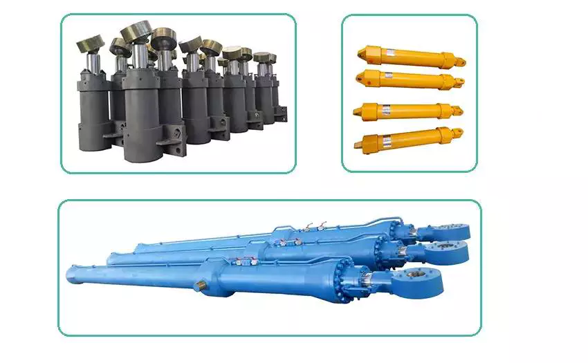
Product Description
Nitrogen Gas Cylinder
Seamless Steel Nitrogen Gas Cylinder 50L X 2 Fax:
| Material: | Steel |
|---|---|
| Usage: | |
| Structure: | General Cylinder |
| Power: | Hydraulic |
| Standard: | Standard |
| Pressure Direction: | Double-acting Cylinder |
| Customization: |
Available
|
|
|---|
How do hydraulic cylinders compare to other methods of force generation like electric motors?
Hydraulic cylinders and electric motors are two different methods of force generation with distinct characteristics and applications. While both hydraulic cylinders and electric motors can generate force, they differ in terms of their working principles, performance attributes, and suitability for specific applications. Here’s a detailed comparison of hydraulic cylinders and electric motors:
1. Working Principle:
– Hydraulic Cylinders: Hydraulic cylinders generate force through the conversion of fluid pressure into linear motion. They consist of a cylinder barrel, piston, piston rod, and hydraulic fluid. When pressurized hydraulic fluid enters the cylinder, it pushes against the piston, causing the piston rod to extend or retract, thereby generating linear force.
– Electric Motors: Electric motors generate force through the conversion of electrical energy into rotational motion. They consist of a stator, rotor, and electromagnetic field. When an electrical current is applied to the motor’s windings, it creates a magnetic field that interacts with the rotor, causing it to rotate and generate torque.
2. Force and Power:
– Hydraulic Cylinders: Hydraulic cylinders are known for their high force capabilities. They can generate substantial linear forces, making them suitable for heavy-duty applications that require lifting, pushing, or pulling large loads. Hydraulic systems can provide high force output even at low speeds, allowing for precise control over force application. However, hydraulic systems typically operate at lower speeds compared to electric motors.
– Electric Motors: Electric motors excel in providing high rotational speeds and are commonly used for applications that require rapid motion. While electric motors can generate significant torque, they tend to have lower force output compared to hydraulic cylinders. Electric motors are suitable for applications that involve continuous rotary motion, such as driving conveyor belts, rotating machinery, or powering vehicles.
3. Control and Precision:
– Hydraulic Cylinders: Hydraulic systems offer excellent control over force, speed, and positioning. By regulating the flow of hydraulic fluid, the force and speed of hydraulic cylinders can be precisely controlled. Hydraulic systems can provide gradual acceleration and deceleration, allowing for smooth and precise movements. This level of control makes hydraulic cylinders well-suited for applications that require precise positioning, such as in industrial automation or construction equipment.
– Electric Motors: Electric motors also offer precise control over speed and positioning. Through motor control techniques such as varying voltage, frequency, or pulse width modulation (PWM), the rotational speed and position of electric motors can be accurately controlled. Electric motors are commonly used in applications that require precise speed control, such as robotics, CNC machines, or servo systems.
4. Efficiency and Energy Consumption:
– Hydraulic Cylinders: Hydraulic systems can be highly efficient, especially when properly sized and designed. However, hydraulic systems typically have higher energy losses due to factors such as fluid leakage, friction, and heat generation. The overall efficiency of a hydraulic system depends on the design, component selection, and maintenance practices. Hydraulic systems require a hydraulic power unit to pressurize the hydraulic fluid, which consumes additional energy.
– Electric Motors: Electric motors can have high efficiency, especially when operated at their optimal operating conditions. Electric motors have lower energy losses compared to hydraulic systems, primarily due to the absence of fluid leakage and lower friction losses. The overall efficiency of an electric motor depends on factors such as motor design, load conditions, and control techniques. Electric motors require an electrical power source, and their energy consumption depends on the motor’s power rating and the duration of operation.
5. Environmental Considerations:
– Hydraulic Cylinders: Hydraulic systems typically use hydraulic fluids that can pose environmental concerns if they leak or are not properly disposed of. The choice of hydraulic fluid can impact factors such as biodegradability, toxicity, and potential environmental hazards. Proper maintenance and leak prevention practices are essential to minimize the environmental impact of hydraulic systems.
– Electric Motors: Electric motors are generally considered more environmentally friendly since they do not require hydraulic fluids. However, the environmental impact of electric motors depends on the source of electricity used to power them. When powered by renewable energy sources, such as solar or wind, electric motors can offer a greener solution compared to hydraulic systems.
6. Application Suitability:
– Hydraulic Cylinders: Hydraulic cylinders are commonly used in applications that require high force output, precise control, and durability. They are widely employed in industries such as construction, manufacturing, mining, and aerospace. Hydraulic systems are well-suited for heavy-duty applications, such as lifting heavy objects, operating heavy machinery, or controlling large-scale movements.
– Electric Motors: Electric motors are widely used in various industries and applications that require rotational motion, speed control, and precise positioning. They are commonly found in appliances, transportation, robotics, HVAC systems, and automation. Electric motorsare suitable for applications that involve continuous rotary motion, such as driving conveyor belts, rotating machinery, or powering vehicles.In summary, hydraulic cylinders and electric motors have different working principles, force capabilities, control characteristics, efficiency levels, and application suitability. Hydraulic cylinders excel in providing high force output, precise control, and durability, making them ideal for heavy-duty applications. Electric motors, on the other hand, offer high rotational speeds, precise speed control, and are commonly used for applications that involve continuous rotary motion. The choice between hydraulic cylinders and electric motors depends on the specific requirements of the application, including the type of motion, force output, control precision, and environmental considerations.
Integration of Hydraulic Cylinders with Equipment Requiring Rapid and Dynamic Movements
Hydraulic cylinders can indeed be integrated with equipment that requires rapid and dynamic movements. While hydraulic systems are generally known for their ability to provide high force and precise control, they can also be designed and optimized for applications that demand fast and dynamic motion. Let’s explore how hydraulic cylinders can be integrated with such equipment:
- High-Speed Hydraulic Systems: Hydraulic cylinders can be part of high-speed hydraulic systems designed specifically for rapid and dynamic movements. These systems incorporate features such as high-flow valves, optimized hydraulic circuitry, and responsive control systems. By carefully engineering the system components and hydraulic parameters, it is possible to achieve the desired speed and responsiveness, enabling the equipment to perform rapid movements.
- Valve Control: The control of hydraulic cylinders plays a crucial role in achieving rapid and dynamic movements. Proportional or servo valves can be used to precisely control the flow of hydraulic fluid into and out of the cylinder. These valves offer fast response times and precise flow control, allowing for rapid acceleration and deceleration of the cylinder’s piston. By adjusting the valve settings and optimizing the control algorithms, equipment can be designed to execute dynamic movements with high speed and accuracy.
- Optimized Cylinder Design: The design of hydraulic cylinders can be optimized to facilitate rapid and dynamic movements. Lightweight materials, such as aluminum alloys or composite materials, can be used to reduce the moving mass of the cylinder, enabling faster acceleration and deceleration. Additionally, the cylinder’s internal components, such as the piston and seals, can be designed for low friction to minimize energy losses and enhance responsiveness. These design optimizations contribute to the overall speed and dynamic performance of the equipment.
- Accumulator Integration: Hydraulic accumulators can be integrated into the system to enhance the dynamic capabilities of hydraulic cylinders. Accumulators store pressurized hydraulic fluid, which can be rapidly released to supplement the flow from the pump during high-demand situations. This stored energy can provide an extra boost of power, allowing for faster and more dynamic movements. By strategically sizing and configuring the accumulator, the system can be optimized for the specific rapid and dynamic requirements of the equipment.
- System Feedback and Control: To achieve precise and dynamic movements, hydraulic systems can incorporate feedback sensors and advanced control algorithms. Position sensors, such as linear potentiometers or magnetostrictive sensors, provide real-time position feedback of the hydraulic cylinder. This information can be used in closed-loop control systems to maintain precise positioning and execute rapid movements. Advanced control algorithms can optimize the control signals sent to the valves, ensuring smooth and dynamic motion while minimizing overshooting or oscillations.
In summary, hydraulic cylinders can be integrated with equipment that requires rapid and dynamic movements by utilizing high-speed hydraulic systems, employing responsive valve control, optimizing cylinder design, integrating accumulators, and incorporating feedback sensors and advanced control algorithms. These measures enable hydraulic systems to deliver the speed, responsiveness, and precision necessary for equipment operating in dynamic environments. By leveraging the capabilities of hydraulic cylinders, manufacturers can design and integrate systems that meet the requirements of applications demanding rapid and dynamic movements.
How do hydraulic cylinders accommodate variations in stroke length and force requirements?
Hydraulic cylinders are designed to accommodate variations in stroke length and force requirements, providing flexibility and adaptability for different applications. They can be tailored to meet specific needs by considering factors such as piston diameter, rod diameter, hydraulic pressure, and cylinder design. Here’s a detailed explanation of how hydraulic cylinders accommodate variations in stroke length and force requirements:
1. Cylinder Size and Design:
– Hydraulic cylinders come in various sizes and designs to accommodate different stroke lengths and force requirements. The cylinder’s diameter, piston area, and rod diameter are key factors that determine the force output. Larger cylinder diameters and piston areas can generate greater force, while smaller diameters are suitable for applications requiring lower force. By selecting the appropriate cylinder size and design, stroke lengths and force requirements can be effectively accommodated.
2. Piston and Rod Configurations:
– Hydraulic cylinders can be designed with different piston and rod configurations to accommodate variations in stroke length. Single-acting cylinders have a single piston and can provide a stroke in one direction. Double-acting cylinders have a piston on both sides, allowing for strokes in both directions. Telescopic cylinders consist of multiple stages that can extend and retract, providing a longer stroke length compared to standard cylinders. By selecting the appropriate piston and rod configuration, the desired stroke length can be achieved.
3. Hydraulic Pressure and Flow:
– The hydraulic pressure and flow rate supplied to the cylinder play a crucial role in accommodating variations in force requirements. Increasing the hydraulic pressure increases the force output of the cylinder, enabling it to handle higher force requirements. By adjusting the pressure and flow rate through hydraulic valves and pumps, the force output can be controlled and matched to the specific requirements of the application.
4. Customization and Tailoring:
– Hydraulic cylinders can be customized and tailored to meet specific stroke length and force requirements. Manufacturers offer a wide range of cylinder sizes, stroke lengths, and force capacities to choose from. Additionally, custom-designed cylinders can be manufactured to suit unique applications with specific stroke length and force demands. By working closely with hydraulic cylinder manufacturers, it is possible to obtain cylinders that precisely match the required stroke length and force requirements.
5. Multiple Cylinders and Synchronization:
– In applications that require high force or longer stroke lengths, multiple hydraulic cylinders can be used in combination. By synchronizing the movement of multiple cylinders through the hydraulic system, the stroke length and force output can be effectively increased. Synchronization can be achieved using mechanical linkages, electronic controls, or hydraulic circuitry, ensuring coordinated movement and force distribution across the cylinders.
6. Load-Sensing and Pressure Control:
– Hydraulic systems can incorporate load-sensing and pressure control mechanisms to accommodate variations in force requirements. Load-sensing systems monitor the load demand and adjust the hydraulic pressure accordingly, ensuring that the cylinder delivers the required force without exerting excessive force. Pressure control valves regulate the pressure within the hydraulic system, allowing for precise control and adjustment of the force output based on the application’s needs.
7. Safety Considerations:
– When accommodating variations in stroke length and force requirements, it is essential to consider safety factors. Hydraulic cylinders should be selected and designed with an appropriate safety margin to handle unexpected loads or variations in operating conditions. Safety mechanisms such as overload protection valves and pressure relief valves can be incorporated to prevent damage or failure in situations where the force limits are exceeded.
By considering factors such as cylinder size and design, piston and rod configurations, hydraulic pressure and flow, customization options, synchronization, load-sensing, pressure control, and safety considerations, hydraulic cylinders can effectively accommodate variations in stroke length and force requirements. This flexibility allows hydraulic cylinders to be tailored to meet the specific demands of a wide range of applications, ensuring optimal performance and efficiency.


editor by CX 2023-12-08
China Professional 2022 Hot Sale New Design Seamless Steel O2 CO2 Industrial Gas Cylinder near me factory
Product Description
Product Description
Product name: seamless steel gas cylinder/industrial gas cylinder
Executive standard: ISO9809-1(TPED),UN ISO9809-1,GB/T5099.1
Hydraulic test pressure, Bar: 250bar/300bar
Nominal working pressure, Bar: 150bar/200bar
Material: 37Mn/34CrMo4
Filling medium: oxygen, nitrogen, carbon dioxide, etc.
Diameter (mm): 219mm~325mm
Exporting countries: China, Mexico, South America, Southeast Asia, Turkey, etc.
Nominal water volume (L): 20L~120L
Length (mm): 660mm~1850mm
Use scenario: filling industrial gas, bottle group
Weight (kg): 26.0KG~120.0KG
Company Profile
Welcome to ZheJiang Clean Energy Co. Ltd.
ZheJiang Clean Energy Co., Ltd. is an enterprise that produces and sells various seamless steel cylinders and CZPT liner gas cylinders such as compressed natural gas cylinders for vehicles, industrial gas cylinders, and fire-fighting cylinders.The company is committed to providing automotive green energy solutions and related environmental protection supporting services.
Our factory
The company was established in 2009 and entered the Xihu (West Lake) Dis. County Economic Development Zone in ZheJiang in 2014. It has built a standardized factory covering an area of 46,000 square meters.The company has focused on R&D and production for more than 10 years, and its global sales volume has reached 2 million.The company has 6 gas cylinder spinning production lines, 2 heat treatment and tempering lines, as well as machining, spraying and winding production lines. It has an annual production capacity of 360,000 gas cylinders, and can produce industrial steel seamless bottles,CNG vehicles, CNG glass fiber hoop wound gas cylinders for CNG vehicles, carbon fiber wound gas cylinders for CNG vehicles, CZPT material wound gas cylinders for CNG vehicles, steel seamless cylinders for CNG stations, fire-fighting steel cylinders, and LPG Cylinders, respirators and other products.
After years of business development, the “Clean” gas cylinder brand has gained a high reputation and reputation in the market. Its sales network covers Asia, Europe, and the Americas. The products are exported to more than 50 countries and regions including Italy, Brazil, Thailand, India, Uzbekistan and so on.Beginning in 2018, Green Gas Cylinders have successively become qualified suppliers for Foton, Xihu (West Lake) Dis.feng, Chery, ZheJiang Automobile and other auto plants.
Quality Control
Related certificates
QMS:ISO9001,IATF16949
PRODUCT CERTIFICATES& APPROVALS:
SEAMLESS STEEL CYLINDER:ISO9809-1(TPED),UNISO9809-1,GB/T5099.1
CNG TYPE-1:ISO11439,ECE R110;
CNG TYPE-2:GB24160,ISO11439,ECE R110;
CNG TYPE-3:Q/LD003-2019,ISO11439;
CNG TYPE-4:ISO11439,ECE R110;
LPG CZPT CYLINDER:EN12245:2009,ISO11119
BREATHING AIR CZPT CYLINDER:EN12245:2009
R&D and patents
ZheJiang Clean Energy had lunched research and development program of Type-4(Plastic liner with carbon fiber full-wrapped)
ZheJiang Clean Energy has been conducting research and development plans for CNG-4 (carbon fiber fully wrapped plastic liner) gas cylinders since 2013. Through the efforts of our technicians, by the end of 2018, we have passed all the test procedures and become the first CNG-4 forensic manufacturer in China. In 2019, we established a modern standardized 6S workshop for CNG-4. At the same time, at the end of 2571, the company successfully completed the research and development of LPG CZPT gas cylinders and obtained relevant international certificates. It is about to complete the construction of the LPG CZPT gas cylinder production line in the first half of 2571 and quickly put it into production.
Exhibition
We arrange to participate in different exhibitions all around the world every year, including FIGAS&VEHIGAS(Peru), ALTFUELS MEXICO(Mexico), GAS FORUM(Russia Federation), GASSUF(Russian Federation), INSTITUCION FERIAL DE MADRID MADRID(Spain), International NGVS Exhibition& Forum(China)
Package&Logistics
We can provide a series of package and logistics solutions according to the customer’s requirements, to ensure our goods reach our customers on time and safely
FAQ
* Q1: Are you manufacturer or trade company?
* A1: We are a Chinese manufacturer, and have been specializing in manufacturing gas cylinders for more than 10 years. Our company brand is “LD”.
* Q2: What is your daily production capacity?
* A2: Our production capacity everyday is 800~1000 units.
* Q3: What is your delivery time?
* A3: Usually our delivery time is 25-45 days against the advance payment. Mainly it depends on when we get the production materials.
* Q4: What certificates do you have?
* A4: We have ISO9001 and IATF16949 for management system, and ISO9809, ISO11439 and ECE R110 for production approval.
* Q5: Do you accept OEM production?
* A5: Of course, we have served several famous motor OEMs, such as TOYOTA(Thailand)-Thailand, IKCO-Iran, GAZ-Russia, DF-China, and FOTON-China, etc. We would like to serve more customers with our superior quality.
* Q6: Can you provide samples to us?
* A6: Yes, we can provide 1-2 samples for your testing freely, but you need to undertake the logistic cost firstly.
* Q7: Can you customize the products?
* A7: Yes, we can provide you with various customized products. For example, your company brand/logo, different accessories and your favorite colors.
What is a pulley?
Pulleys are shafts or wheels on a shaft that support the movement and change of direction of a taut cable. The pulley also transfers power from the shaft to the cable. A simple pulley is used to raise the school flag. Read on to learn about the basic types of pulleys. We also covered the use of pulleys in everyday life. Read on to learn more about this important mechanical part.
composite pulley
A composite pulley is a mechanical system where 2 or more pulleys and ropes are connected together. It reduces the force required to lift the load because the force is divided by the distance of each pulley. Distance is equal to the mass of the object. Composite pulleys are a common mechanical system on sailboats. Composite pulleys can be used to lift heavy equipment such as sails.
The compound pulley unit consists of 2 pulleys, 1 fixed and the other movable. The fixed pulley is fixed overhead, while the movable pulley is connected to the load by a chain. The lift applies force to the other end of the rope. Anchor points are attached to fixed joists, ceiling joists or sturdy branches. The chain should be long enough to support the load during lifting.
Composite pulleys can be made from a variety of materials. Some are fixed and remain fixed. Others are detachable. The composite pulley combines the advantages of both types, making it a versatile tool. In the table below, these 3 types of pulleys are compared. It’s easy to see which 1 is best for your needs. The right choice depends on your specific needs and budget.
The compound pulley system consists of 2 fixed pulleys and 1 movable pulley. The compound pulley system multiplies the force by a factor of 2. The compound pulley system is particularly suitable for heavy loads and is ideal for construction sites. Workers apply less than half the load force on the composite pulley, significantly reducing the force required. This is a major benefit for many people.
Fixed pulley
Fixed pulleys are fixed gears of fixed length that are mounted on solid objects. There are many different types of pulley systems. Some cooperate with each other, but not “fixed”.
Fixed pulleys can be used for a variety of purposes. One application is to lift small objects. They have a one-to-1 mechanical advantage. Often, a single pulley can lift small loads. The force required to lift a single fixed pulley remains the same. They are usually used to lift lighter objects. They can even be attached to buckets used to draw water from wells.
While single fixed pulleys have desirable mechanical advantages, they are not suitable for force multipliers. Because their mechanical advantage diminishes over time, they are not effective force multipliers. They are used to redirect work so that it can be applied in the most convenient direction. This mechanical advantage is the main advantage of fixed pulleys and the most common way of moving objects. They have several benefits, including the ability to increase the speed of moving objects.
Another application for fixed pulleys is lifting supplies. A scaffold can weigh more than 1 and can be directly hoisted. In order to facilitate the transportation of materials, fixed pulleys are usually installed on the top of the scaffolding on construction sites. Then thread the rope through the edge of the groove that holds the pulley. The fixed pulley exerts the same force on the pull side as on the push side. The same is true for moving objects with fixed pulleys.
moving pulley
A movable pulley is a device whose part is fixed to another object, usually a rod or beam. The movable part moves with the load, making the load feel lighter. This is a useful tool for those who need to carry heavy items such as large bags. The advantages of moving pulleys are many. Here are some of them. Read on to learn more about them.
One of the most common uses of movable pulley systems is climbing high objects. Climbers act as pulley loads and pull ropes to lift objects. Eventually, when the traction stops, the climber descends. However, it is still a useful tool in other situations. The movable pulley system can help you climb the tallest objects or lift them to level surfaces.
Another example of movable pulleys is in industry. Depending on the load, movable pulleys make handling and moving loads easier. You can use them in a variety of applications in manufacturing and industry, including cleaning. For example, the American flag is raised and lowered every day. Removable pulleys are a handy tool when buildings need cleaning.
If you’re not sure whether a task requires a pulley, a zipline might be a good option. Connect the 2 ends of the rope and the pulley will move along the rope, then attach the rope to the metal cable. The load is the person holding the pulley, and the force comes from the attachment on the other end of the rope. There are 2 types of live pulleys: simple pulleys with just 1 wheel and live pulleys with many ropes attached.
School flag raised with simple pulleys
How is the school flag raised? It is pulled up by a rope attached to a pulley at the top of the pole. When the rope is pulled, the pulley turns, raising the flag. A pulley is a simple mechanism that helps people move heavier objects with ease. The rope must be securely attached to the pulley to keep the flag stable.
A simple pulley is a spinning wheel with grooves on 1 side and ropes on the other. The rope can be any length and the wheels can be any size. The rope has to go through the groove and the load is attached to the other end of the rope. Simple pulleys are pulleys with fixed shafts. An example is the wheel on a school flagpole.
A simple pulley system consists of a primary pole, a secondary pole and an outer member. The primary flagpole is connected to the track by a detour, while the secondary flagpole is connected to the track by a pipe. There is a groove on 1 side of the track, which passes through the inner cavity of the flagpole. An open track at the upper end of the track connects the 2 parts of the pulley.
A simple pulley can be used for many purposes. This is a useful machine that can be used to raise the flag. Among other things, it can be used in clothing lines, bird feeders, and even roofers. And, of course, you can use the pulley to raise the flag. Its versatility makes it an essential part of school decor.
cast iron pulley
If you are looking for pulleys for your machine, you may come across cast iron pulleys. They are usually cheap and available in a variety of sizes. The rim is held in place by a mesh attached to a central boss. The arms and spokes can be straight or curved, but most are oval. There are many uses for this type of pulley.
You might wonder why the arms of cast iron pulleys are so curved. Bent arms tend to yield rather than break. Cast iron pulleys are usually round with a slight bump on the rim, which helps keep the belt centered on the rim as it moves. On a 300mm diameter pulley, the bumps may be as small as 9mm.


China manufacturer Made in China Industry Gas Nitrogen Oxygen CO2 Regulator Oxygen Cylinder near me supplier
Product Description
Product Description
Product name: seamless steel gas cylinder/industrial gas cylinder
Executive standard: ISO9809-1(TPED),UN ISO9809-1,GB/T5099.1
Hydraulic test pressure, Bar: 250bar/300bar
Nominal working pressure, Bar: 150bar/200bar
Material: 37Mn/34CrMo4
Filling medium: oxygen, nitrogen, carbon dioxide, etc.
Diameter (mm): 219mm~325mm
Exporting countries: China, Mexico, South America, Southeast Asia, Turkey, etc.
Nominal water volume (L): 20L~120L
Length (mm): 660mm~1850mm
Use scenario: filling industrial gas, bottle group
Weight (kg): 26.0KG~120.0KG
Company Profile
Welcome to ZheJiang Clean Energy Co. Ltd.
ZheJiang Clean Energy Co., Ltd. is an enterprise that produces and sells various seamless steel cylinders and CZPT liner gas cylinders such as compressed natural gas cylinders for vehicles, industrial gas cylinders, and fire-fighting cylinders.The company is committed to providing automotive green energy solutions and related environmental protection supporting services.
Our factory
The company was established in 2009 and entered the Xihu (West Lake) Dis. County Economic Development Zone in ZheJiang in 2014. It has built a standardized factory covering an area of 46,000 square meters.The company has focused on R&D and production for more than 10 years, and its global sales volume has reached 2 million.The company has 6 gas cylinder spinning production lines, 2 heat treatment and tempering lines, as well as machining, spraying and winding production lines. It has an annual production capacity of 360,000 gas cylinders, and can produce industrial steel seamless bottles,CNG vehicles, CNG glass fiber hoop wound gas cylinders for CNG vehicles, carbon fiber wound gas cylinders for CNG vehicles, CZPT material wound gas cylinders for CNG vehicles, steel seamless cylinders for CNG stations, fire-fighting steel cylinders, and LPG Cylinders, respirators and other products.
After years of business development, the “Clean” gas cylinder brand has gained a high reputation and reputation in the market. Its sales network covers Asia, Europe, and the Americas. The products are exported to more than 50 countries and regions including Italy, Brazil, Thailand, India, Uzbekistan and so on.Beginning in 2018, Green Gas Cylinders have successively become qualified suppliers for Foton, Xihu (West Lake) Dis.feng, Chery, ZheJiang Automobile and other auto plants.
Quality Control
Related certificates
QMS:ISO9001,IATF16949
PRODUCT CERTIFICATES& APPROVALS:
SEAMLESS STEEL CYLINDER:ISO9809-1(TPED),UNISO9809-1,GB/T5099.1
CNG TYPE-1:ISO11439,ECE R110;
CNG TYPE-2:GB24160,ISO11439,ECE R110;
CNG TYPE-3:Q/LD003-2019,ISO11439;
CNG TYPE-4:ISO11439,ECE R110;
LPG CZPT CYLINDER:EN12245:2009,ISO11119
BREATHING AIR CZPT CYLINDER:EN12245:2009
R&D and patents
ZheJiang Clean Energy had lunched research and development program of Type-4(Plastic liner with carbon fiber full-wrapped)
ZheJiang Clean Energy has been conducting research and development plans for CNG-4 (carbon fiber fully wrapped plastic liner) gas cylinders since 2013. Through the efforts of our technicians, by the end of 2018, we have passed all the test procedures and become the first CNG-4 forensic manufacturer in China. In 2019, we established a modern standardized 6S workshop for CNG-4. At the same time, at the end of 2571, the company successfully completed the research and development of LPG CZPT gas cylinders and obtained relevant international certificates. It is about to complete the construction of the LPG CZPT gas cylinder production line in the first half of 2571 and quickly put it into production.
Exhibition
We arrange to participate in different exhibitions all around the world every year, including FIGAS&VEHIGAS(Peru), ALTFUELS MEXICO(Mexico), GAS FORUM(Russia Federation), GASSUF(Russian Federation), INSTITUCION FERIAL DE MADRID MADRID(Spain), International NGVS Exhibition& Forum(China)
Package&Logistics
We can provide a series of package and logistics solutions according to the customer’s requirements, to ensure our goods reach our customers on time and safely
FAQ
* Q1: Are you manufacturer or trade company?
* A1: We are a Chinese manufacturer, and have been specializing in manufacturing gas cylinders for more than 10 years. Our company brand is “LD”.
* Q2: What is your daily production capacity?
* A2: Our production capacity everyday is 800~1000 units.
* Q3: What is your delivery time?
* A3: Usually our delivery time is 25-45 days against the advance payment. Mainly it depends on when we get the production materials.
* Q4: What certificates do you have?
* A4: We have ISO9001 and IATF16949 for management system, and ISO9809, ISO11439 and ECE R110 for production approval.
* Q5: Do you accept OEM production?
* A5: Of course, we have served several famous motor OEMs, such as TOYOTA(Thailand)-Thailand, IKCO-Iran, GAZ-Russia, DF-China, and FOTON-China, etc. We would like to serve more customers with our superior quality.
* Q6: Can you provide samples to us?
* A6: Yes, we can provide 1-2 samples for your testing freely, but you need to undertake the logistic cost firstly.
* Q7: Can you customize the products?
* A7: Yes, we can provide you with various customized products. For example, your company brand/logo, different accessories and your favorite colors.
Types of Bevel Gears
Bevel Gears are used in a number of industries. They are used in wheeled excavators, dredges, conveyor belts, mill actuators, and rail transmissions. A bevel gear’s spiral or angled bevel can make it suitable for confined spaces. It is also used in robotics and vertical supports of rolling mills. You can use bevel gears in food processing processes. For more information on bevel gears, read on.
Spiral bevel gear
Spiral bevel gears are used to transmit power between 2 shafts in a 90-degree orientation. They have curved or oblique teeth and can be fabricated from various metals. Bestagear is 1 manufacturer specializing in medium to large spiral bevel gears. They are used in the mining, metallurgical, marine, and oil fields. Spiral bevel gears are usually made from steel, aluminum, or phenolic materials.
Spiral bevel gears have many advantages. Their mesh teeth create a less abrupt force transfer. They are incredibly durable and are designed to last a long time. They are also less expensive than other right-angle gears. They also tend to last longer, because they are manufactured in pairs. The spiral bevel gear also reduces noise and vibration from its counterparts. Therefore, if you are in need of a new gear set, spiral bevel gears are the right choice.
The contact between spiral bevel gear teeth occurs along the surface of the gear tooth. The contact follows the Hertz theory of elastic contact. This principle holds for small significant dimensions of the contact area and small relative radii of curvature of the surfaces. In this case, strains and friction are negligible. A spiral bevel gear is a common example of an inverted helical gear. This gear is commonly used in mining equipment.
Spiral bevel gears also have a backlash-absorbing feature. This feature helps secure the thickness of the oil film on the gear surface. The shaft axis, mounting distance, and angle errors all affect the tooth contact on a spiral bevel gear. Adjusting backlash helps to correct these problems. The tolerances shown above are common for bevel gears. In some cases, manufacturers make slight design changes late in the production process, which minimizes the risk to OEMs.
Straight bevel gear
Straight bevel gears are among the easiest types of gears to manufacture. The earliest method used to manufacture straight bevel gears was to use a planer equipped with an indexing head. However, improvements have been made in manufacturing methods after the introduction of the Revacycle system and the Coniflex. The latest technology allows for even more precise manufacturing. Both of these manufacturing methods are used by CZPT. Here are some examples of straight bevel gear manufacturing.
A straight bevel gear is manufactured using 2 kinds of bevel surfaces, namely, the Gleason method and the Klingelnberg method. Among the two, the Gleason method is the most common. Unlike other types of gear, the CZPT method is not a universal standard. The Gleason system has higher quality gears, since its adoption of tooth crowning is the most effective way to make gears that tolerate even small assembly errors. It also eliminates the stress concentration in the bevelled edges of the teeth.
The gear’s composition depends on the application. When durability is required, a gear is made of cast iron. The pinion is usually 3 times harder than the gear, which helps balance wear. Other materials, such as carbon steel, are cheaper, but are less resistant to corrosion. Inertia is another critical factor to consider, since heavier gears are more difficult to reverse and stop. Precision requirements may include the gear pitch and diameter, as well as the pressure angle.
Involute geometry of a straight bevel gear is often computed by varying the surface’s normal to the surface. Involute geometry is computed by incorporating the surface coordinates and the theoretical tooth thickness. Using the CMM, the spherical involute surface can be used to determine tooth contact patterns. This method is useful when a roll tester tooling is unavailable, because it can predict the teeth’ contact pattern.
Hypoid bevel gear
Hypoid bevel gears are an efficient and versatile speed reduction solution. Their compact size, high efficiency, low noise and heat generation, and long life make them a popular choice in the power transmission and motion control industries. The following are some of the benefits of hypoid gearing and why you should use it. Listed below are some of the key misperceptions and false assumptions of this gear type. These assumptions may seem counterintuitive at first, but will help you understand what this gear is all about.
The basic concept of hypoid gears is that they use 2 non-intersecting shafts. The smaller gear shaft is offset from the larger gear shaft, allowing them to mesh without interference and support each other securely. The resulting torque transfer is improved when compared to conventional gear sets. A hypoid bevel gear is used to drive the rear axle of an automobile. It increases the flexibility of machine design and allows the axes to be freely adjusted.
In the first case, the mesh of the 2 bodies is obtained by fitting the hyperboloidal cutter to the desired gear. Its geometric properties, orientation, and position determine the desired gear. The latter is used if the desired gear is noise-free or is required to reduce vibrations. A hyperboloidal cutter, on the other hand, meshes with 2 toothed bodies. It is the most efficient option for modeling hypoid gears with noise concerns.
The main difference between hypoid and spiral bevel gears is that the hypoid bevel gear has a larger diameter than its counterparts. They are usually found in 1:1 and 2:1 applications, but some manufacturers also provide higher ratios. A hypoid gearbox can achieve speeds of 3 thousand rpm. This makes it the preferred choice in a variety of applications. So, if you’re looking for a gearbox with a high efficiency, this is the gear for you.
Addendum and dedendum angles
The addendum and dedendum angles of a bevel gear are used to describe the shape and depth of the teeth of the gear. Each tooth of the gear has a slightly tapered surface that changes in depth. These angles are defined by their addendum and dedendum distances. Addendum angle is the distance between the top land and the bottom surface of the teeth, while dedendum angle is the distance between the pitch surface and the bottom surface of the teeth.
The pitch angle is the angle formed by the apex point of the gear’s pitch cone with the pitch line of the gear shaft. The dedendum angle, on the other hand, is the depth of the tooth space below the pitch line. Both angles are used to measure the shape of a bevel gear. The addendum and dedendum angles are important for gear design.
The dedendum and addendum angles of a bevel gear are determined by the base contact ratio (Mc) of the 2 gears. The involute curve is not allowed to extend within the base diameter of the bevel gear. The base diameter is also a critical measurement for the design of a gear. It is possible to reduce the involute curve to match the involute curve, but it must be tangential to the involute curve.
The most common application of a bevel gear is the automotive differential. They are used in many types of vehicles, including cars, trucks, and even construction equipment. They are also used in the marine industry and aviation. Aside from these 2 common uses, there are many other uses for bevel gears. And they are still growing in popularity. But they’re a valuable part of automotive and industrial gearing systems.
Applications of bevel gears
Bevel gears are used in a variety of applications. They are made of various materials depending on their weight, load, and application. For high-load applications, ferrous metals such as grey cast iron are used. These materials have excellent wear resistance and are inexpensive. For lower-weight applications, steel or non-metals such as plastics are used. Some bevel gear materials are considered noiseless. Here are some of their most common uses.
Straight bevel gears are the easiest to manufacture. The earliest method of manufacturing them was with a planer with an indexing head. Modern manufacturing methods introduced the Revacycle and Coniflex systems. For industrial gear manufacturing, the CZPT uses the Revacycle system. However, there are many types of bevel gears. This guide will help you choose the right material for your next project. These materials can withstand high rotational speeds and are very strong.
Bevel gears are most common in automotive and industrial machinery. They connect the driveshaft to the wheels. Some even have a 45-degree bevel. These gears can be placed on a bevel surface and be tested for their transmission capabilities. They are also used in testing applications to ensure proper motion transmission. They can reduce the speed of straight shafts. Bevel gears can be used in many industries, from marine to aviation.
The simplest type of bevel gear is the miter gear, which has a 1:1 ratio. It is used to change the axis of rotation. The shafts of angular miter bevel gears can intersect at any angle, from 45 degrees to 120 degrees. The teeth on the bevel gear can be straight, spiral, or Zerol. And as with the rack and pinion gears, there are different types of bevel gears.